
An N-PE spark gap SPD is the dedicated surge protection path installed between neutral and protective earth in many 3+1 and 1+1 arrangements. It may also be described as an N-PE surge arrester, N-PE lightning current arrester or N-PE spark-gap protection module.
For panel builders and OEM buyers, the important question is not only what the component is. You need to know why it is used in TT systems, how it differs from an ordinary MOV module, and which path-specific data must be verified before approving the complete SPD.
Table of Contents
Quick Answer: What Is an N-PE Spark Gap SPD?
An N-PE spark gap SPD is a voltage-switching element connected between neutral and protective earth. During normal operation, it remains in a high-impedance state. During a surge, it switches into conduction and provides a discharge path from N to PE.
In a typical three-phase 3+1 SPD, three voltage-limiting paths protect L1-N, L2-N and L3-N. The fourth path protects N-PE. Spark-gap-based N-PE arresters are used in documented 3+1 and 1+1 configurations for TT and selected TN systems, subject to the installation design and manufacturer instructions.[3][5]
| Protection path | Typical function | Main buyer checks |
|---|---|---|
| L1-N, L2-N, L3-N | Limit phase-to-neutral surge voltage | Uc, Up, In, Imax or Iimp |
| N-PE | Provide the common neutral-to-earth discharge path | Uc, Up, TOV, follow current, In or Iimp |
Buyer meaning: never approve a “4P SPD” only by pole count. Confirm whether the internal circuit is 3+1 or 4+0 and verify the N-PE path separately.
What Does N-PE Protection Mean?
N means neutral. PE means protective earth. N-PE protection means that the SPD includes a defined surge protection path between these two conductors.
The N-PE path is not intended to carry normal load current. Its purpose is to control excessive voltage between neutral and earth during a transient event.
In a 3+1 arrangement, surge current from the phase conductors is first handled by the three L-N paths. The N-PE element then provides the shared discharge route toward protective earth.
Why Are 3+1 SPDs Common in TT Systems?
In a TT system, the installation protective earth is connected to a local earthing arrangement. Neutral is connected to the source earthing point. N and PE remain separate within the installation.
A 3+1 arrangement allows the three phase-to-neutral protection paths to work together with one dedicated neutral-to-earth path. IEC 61643-12 provides principles for selecting, locating and coordinating AC SPDs, while IEC 60364-5-53 covers the selection and erection of devices used in low-voltage installations.[3][4]
Official manufacturer documentation also identifies spark-gap-based N-PE arresters for 3+1 and 1+1 arrangements in TT systems and, depending on the product and design, selected TN systems.[5]
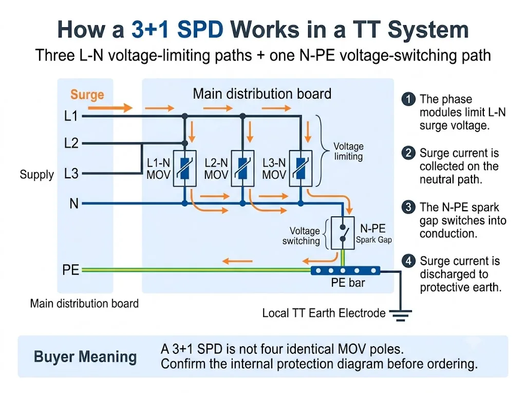
For a broader system-level explanation, see the TT System SPD Guide. This page stays focused on the N-PE spark gap module and its procurement meaning.
3+1 vs 4+0: What Changes Inside the SPD?
Both arrangements may be sold in housings that appear to have four poles. The important difference is the internal protection topology.
The most important column is “Protection paths.” It shows why pole count alone is not enough.
| Arrangement | Protection paths | N-PE function | Buyer must confirm |
|---|---|---|---|
| 3+1 | L1-N, L2-N, L3-N plus N-PE | Shared final discharge path from neutral to earth | N-PE technology, ratings and total assembly data |
| 4+0 | L1-PE, L2-PE, L3-PE and N-PE, or another declared conductor-to-PE arrangement | One of four conductor-to-PE paths rather than the “+1” common path | Exact circuit, technology and suitability for the earthing system |
Procurement conclusion: “3P+N,” “4P,” “3+1” and “4+0” are not always used consistently across markets. Request the internal circuit diagram.
The detailed comparison of complete four-pole configurations belongs in the 3P+N vs 4P SPD Guide. For this page, the key point is that a 3+1 SPD gives the N-PE module a specific shared-discharge role.
What Does the Spark Gap Do in the N-PE Path?
A spark gap is a voltage-switching protection element. It remains highly insulating during normal operation. When its switching condition is reached during a surge, it changes rapidly into a conducting state.
After the surge has passed, an AC spark-gap-based SPD may also need to extinguish current supplied by the power system. IEC 61643-01 and IEC 61643-11 include requirements concerning SPDs and modes of protection with follow current.[1][2]
In practical N-PE selection, three characteristics deserve special attention:
- High insulation between neutral and earth during normal operation
- Declared surge-current capability during operation
- TOV and follow-current behaviour under abnormal AC conditions
N-PE Spark Gap vs Ordinary MOV Module
An N-PE spark gap and an MOV module should not be compared as though they were interchangeable components. They use different operating principles and normally protect different paths inside the 3+1 arrangement.
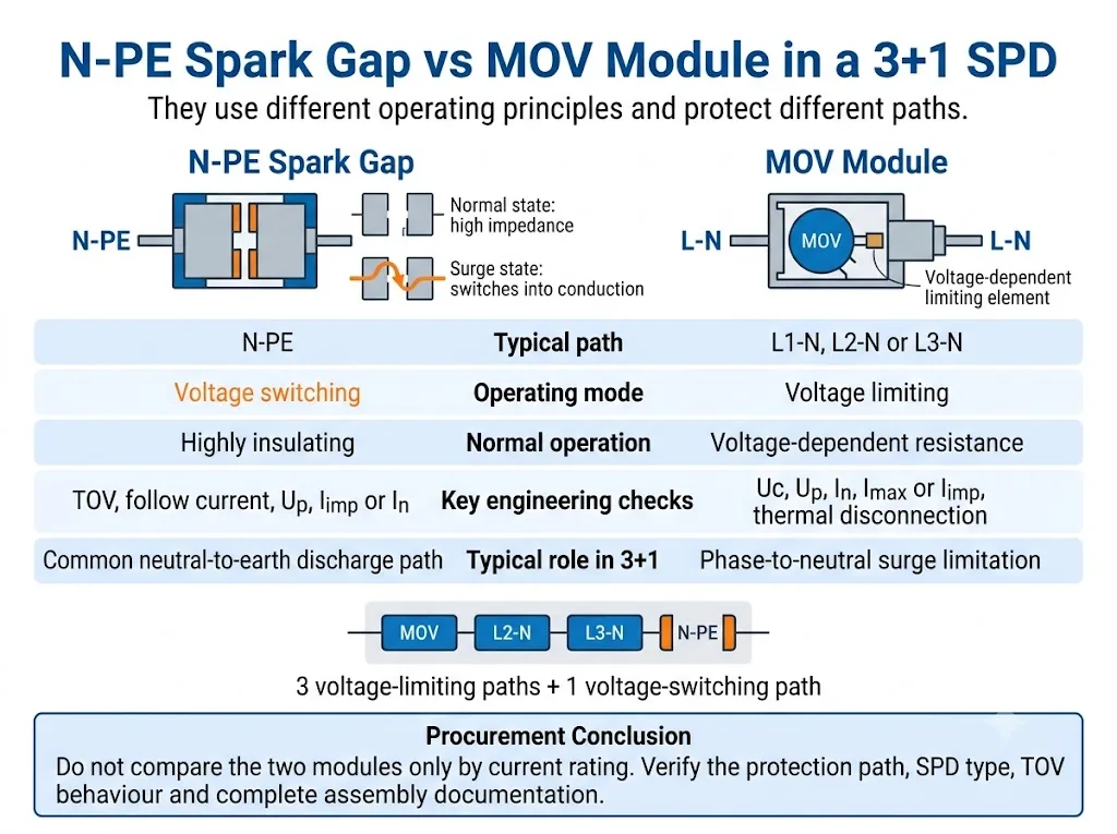
Compare the protection role first. Current rating alone does not show whether two modules perform the same function.
| Decision point | N-PE spark gap | MOV module |
|---|---|---|
| Operating principle | Voltage switching | Voltage limiting |
| Typical 3+1 path | N-PE | L1-N, L2-N or L3-N |
| Normal state | Highly insulating before sparkover | Voltage-dependent resistance |
| Key AC checks | TOV and follow-current behaviour | Thermal stability and disconnection |
| Key ratings | Uc, Up, In or Iimp, total current where declared | Uc, Up, In, Imax or Iimp |
Procurement conclusion: neither technology is universally better. Suitability depends on the protection path, SPD classification and declared performance of the complete assembly.
For a broader comparison of the two operating technologies, see the Spark Gap vs MOV SPD Guide.
Is an N-PE Spark Gap Always a Type 1 SPD?
No. Spark-gap technology does not automatically make the complete SPD a Type 1 device.
Official product documentation shows both Type 1 N-PE lightning current arresters and Type 2 N-PE spark-gap devices. The classification must be confirmed from the declaration and test documentation for the complete SPD or declared mode of protection.[2][5][6]
The key difference is the declared test classification, not the visual appearance of the N-PE cartridge.
| Item | Type 1 N-PE path | Type 2 N-PE path |
|---|---|---|
| Main impulse test | Iimp with 10/350 µs current waveform | In and commonly Imax with 8/20 µs current waveform |
| Typical project role | Lightning-current handling at a relevant entry position | Surge limitation and coordinated downstream protection |
| Technology | May use a spark gap | May also use a spark gap |
| Approval evidence | Complete Type 1 or Type 1+2 declaration | Complete Type 2 declaration |
Buyer warning: do not infer Type 1 performance from the words “spark gap,” “N-PE” or “lightning protection” alone.
How Does the N-PE Module Affect RCD Coordination?
TT installations commonly use residual-current devices as part of the fault-protection arrangement. The SPD position and RCD arrangement therefore need to be reviewed together.
A spark-gap-based N-PE path normally provides very high insulation during ordinary operation. This can help avoid a continuously conductive or continuously voltage-stressed neutral-to-earth path.
However, surge current discharged through an SPD can still affect an RCD. The result depends on the device positions, RCD characteristics, earthing system, SPD protection modes and installation arrangement. IEC 61643-12 addresses SPD selection, location and coordination, while IEC 60364-5-53 provides the installation framework that must be applied to the actual project.[3][4]
The installation details, connection length, backup protection and RCD relationship are covered more fully in the IEC 60364-5-534 SPD Installation Guide.
Which N-PE Parameters Must Buyers Verify?
1. Declared protection mode
The datasheet or circuit diagram should clearly identify the N-PE path. Do not infer the protection mode from the cartridge colour or its position in the housing.
2. Maximum continuous operating voltage, Uc
Confirm the Uc declared for the N-PE path. It may not be the same value used for the L-N phase modules.
3. Voltage protection level, Up
Check the declared Up for N-PE as well as the protection level of the complete mode or assembly. IEC 61643-01 and IEC 61643-11 distinguish testing of complete SPDs, modes of protection and SPD assemblies.[1][2]
4. Iimp, In and Imax
For Type 1 performance, verify Iimp using the 10/350 µs waveform. For Type 2 performance, verify In and, where declared, Imax using the 8/20 µs waveform.
5. Total discharge capability
Some 3+1 products declare total current for the complete arrangement or the shared N-PE path. Do not confuse this value with the rating of one L-N cartridge.
6. Temporary overvoltage behaviour
TOV is a power-frequency overvoltage lasting much longer than a surge impulse. Confirm whether the product withstands the declared condition or enters a defined safe-failure mode. Product-specific TOV data must be taken from the exact model documentation.[7][8]
7. Follow-current extinguishing capability
Where follow current is relevant and declared, confirm the extinguishing capability of the N-PE spark gap. Do not assume that every spark-gap design has the same behaviour.[2][8]
8. Backup protection and short-circuit data
Confirm the required upstream fuse or circuit breaker and the short-circuit capability of the complete SPD. Do not select backup protection from a single cartridge value.
9. Replacement, status indication and remote signalling
Check whether the N-PE element is replaceable, whether it has visual status indication and whether the remote contact monitors the complete assembly.
How to Verify a 3+1 SPD Before OEM or Project Approval
The safest purchasing process is to confirm the system first, then the internal protection arrangement, and only after that approve the electrical ratings and physical model.
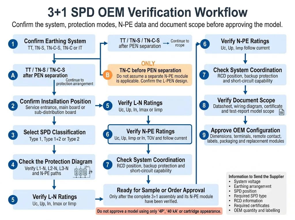
- Confirm the earthing system. Identify whether the installation is TT, TN-S, TN-C-S, TN-C or IT. For TN-C-S, state whether the SPD is installed before or after PEN separation.
- Confirm the installation position. State whether the SPD is at the service entrance, main distribution board or downstream distribution board.
- Select the required SPD classification. Confirm whether the project requires Type 1, Type 1+2 or Type 2 performance.
- Verify the internal circuit. Confirm 1+1, 3+1, 4+0 or another declared arrangement from the wiring diagram.
- Check the L-N and N-PE paths separately. Verify Uc, Up and the applicable discharge-current ratings for each part.
- Review TOV and follow-current behaviour. Use the exact model datasheet. Do not substitute values from a similar-looking product.
- Check system coordination. Confirm RCD position, backup protection and short-circuit requirements.
- Verify the document scope. Confirm that the datasheet, certificate, test report and installation instructions cover the actual complete assembly.
- Approve the OEM configuration. Confirm dimensions, terminals, remote contact, cartridge coding, labels, packaging and replacement references.
What Evidence Should Support Project Approval?
Technical graphics explain the circuit, but project approval should rely on model-specific evidence. Buyers should request documents that identify the exact assembly and its N-PE module.
Shows whether the complete product is 3+1, 4+0 or another protection arrangement.
Lists the L-N and N-PE ratings, TOV data, protection level and backup requirements.
Confirms which model, configuration and standard edition are actually covered.
Defines the approved terminals, conductor arrangement, backup protection and replacement process.
LEEYEE model recommendations should be confirmed against the current model-specific datasheet, drawing and available conformity documents before sampling or order approval. CNSPD is LEEYEE’s surge-protection-focused platform for global technical buyers.
Common Mistakes When Ordering an N-PE or 3+1 SPD
Ordering only by “4P”
Four visible modules do not prove that the product uses a 3+1 circuit.
Treating all four modules as identical
The N-PE spark gap may use different technology and different parameters from the three L-N modules.
Assuming every spark gap is Type 1
Type 2 N-PE spark-gap products also exist. Confirm the complete SPD classification.[6]
Comparing only Imax
Imax alone does not explain Type 1 capability, TOV behaviour, follow current, voltage protection level or the rating of the complete 3+1 assembly.
Ignoring the RCD position
The same SPD may interact differently with the installation depending on the RCD type, location and wiring arrangement.
Replacing a cartridge by appearance
Similar housings may have different Uc values, coding, protection modes or base compatibility.
Checking documents for only one module
A cartridge datasheet does not automatically prove that the complete 3+1 assembly has the required test or certificate scope.
Before Ordering, Prepare These Details
- Nominal system voltage and frequency
- TT, TN-S, TN-C-S, TN-C or IT system
- SPD installation position
- Required Type 1, Type 1+2 or Type 2 classification
- Required 1+1, 3+1, 4+0 or other arrangement
- L-N and N-PE Uc values
- L-N and N-PE Up values
- Required Iimp, In, Imax or total current
- N-PE TOV behaviour
- Follow-current requirement where applicable
- Backup fuse or circuit-breaker information
- RCD type and installation position
- Remote signalling requirement
- DIN-rail width and terminal arrangement
- Required standard and certificate scope
- OEM label, packaging, quantity and replacement modules
Confirm an N-PE or 3+1 SPD Configuration
Send the system voltage, earthing arrangement, installation position, required SPD type, RCD information, protection diagram and discharge-current requirements.
LEEYEE can use these details to review the requested configuration and prepare a model recommendation for distribution boards, project supply or OEM approval. The final selection remains subject to the project design, applicable rules and model-specific documentation.
Confirm an OEM SPD ConfigurationFAQ About N-PE Spark Gap SPDs
What does N-PE mean on an SPD?
N-PE identifies a surge protection path between neutral and protective earth. In many 3+1 products, this path uses a voltage-switching spark gap.
Why is an N-PE spark gap used in a 3+1 SPD?
The N-PE path performs a different function from the three L-N paths. It provides the shared neutral-to-earth discharge route while remaining highly insulating during normal operation.
Is a 3+1 SPD the same as any four-pole SPD?
No. A four-pole product may use 3+1, 4+0 or another declared arrangement. The internal circuit diagram is required.
Is every N-PE spark gap a Type 1 device?
No. Official product documentation shows both Type 1 N-PE lightning current arresters and Type 2 N-PE spark-gap devices.[5][6]
Can an MOV module replace an N-PE spark gap cartridge?
Not without technical approval. The operating principle, protection mode, TOV behaviour, follow-current behaviour and complete assembly coordination may be different.
Does an N-PE spark gap prevent RCD nuisance tripping?
It can provide high insulation during normal operation, but it cannot guarantee that an RCD will never operate. Coordination depends on the SPD position, RCD characteristics and installation arrangement.
Should the N-PE module have the same current rating as the phase modules?
Not automatically. The shared N-PE path may be declared using different path-specific or total-current data. Use the complete assembly documentation.
Which documents should an OEM buyer request?
Request the circuit diagram, model-specific datasheet, installation instructions, backup-protection information, certificate or test-report scope, dimensional drawing and replacement-module references.
References
- International Electrotechnical Commission, IEC 61643-01:2024, Low-voltage surge protective devices — Part 01: General Requirements and test methods. Official IEC publication page.
- International Electrotechnical Commission, IEC 61643-11:2025, Low-voltage surge protective devices — Part 11: Surge protective devices connected to AC low-voltage power systems — Requirements and test methods. Official IEC publication page.
- International Electrotechnical Commission, IEC 61643-12:2020, Low-voltage surge protective devices — Part 12: Surge protective devices connected to low-voltage power systems — Selection and application principles. Official IEC publication page.
- International Electrotechnical Commission, IEC 60364-5-53:2019+AMD1:2020+AMD2:2024 CSV, Low-voltage electrical installations — Part 5-53: Selection and erection of electrical equipment — Devices for protection for safety, isolation, switching, control and monitoring. Official IEC publication page.
- DEHN, N-PE Lightning Current Arresters, official application and product-category information for spark-gap-based Type 1 N-PE arresters used in 3+1 and 1+1 arrangements. Official DEHN page.
- Phoenix Contact, VAL-ME-N/PE — Type 2 Surge Protection Device, official product information identifying a Type 2 arrester as an N-PE spark gap. Official Phoenix Contact page.
- OBO Bettermann, V20 Surge Arrester, Leakage Current-Free, 3-Pole + NPE, official model-specific TOV and product data. Official OBO page.
- OBO Bettermann, V20 Surge Arrester with Integrated Pre-Fuse, 3+NPE, official model-specific TOV, backup protection and N-PE follow-current data. Official OBO page.
