
An SPD may survive a very high lightning impulse but fail during a much lower voltage that remains for seconds or longer. This longer abnormal voltage is called a temporary overvoltage, or TOV.
For OEM buyers and panel builders, TOV withstand is a procurement-risk parameter. It helps determine whether an SPD can remain stable, disconnect in a controlled manner or suffer serious damage when the system voltage rises beyond its intended continuous operating range.
Table of Contents
What Is SPD TOV Withstand?
A surge is a short transient event that an SPD is intended to limit. A TOV is an abnormal power-frequency or DC voltage that remains long enough to create sustained electrical and thermal stress.[1][2][4]
TOV withstand is not one standalone voltage number. A meaningful declaration must identify the protection mode, applied voltage, duration and expected result.
- Uc or Ucpv covers continuous voltage. The real operating voltage must remain within the declared rating.
- UT describes a defined abnormal condition. It must be read together with duration and test outcome.
- Low Uc can increase TOV sensitivity. Sustained MOV conduction may cause heating and disconnection.
- High Imax does not prove TOV strength. Impulse-current and sustained-voltage risks are different.
Quick Approval Decision for Buyers
Use this table before approving a sample, BOM item or private-label model. It is a screening tool, not a substitute for project engineering.
| Decision | Finding | Required action |
|---|---|---|
| Approve | The exact model data matches the system voltage, protection mode, TOV condition and short-circuit requirements. | Proceed to sample or BOM approval, subject to the complete project review. |
| Hold | UT is shown without duration, the safe-failure result is unclear, or the certificate scope does not identify the exact model. | Request the missing test condition, report scope and installation information. |
| Reject | The normal maximum voltage exceeds Uc or Ucpv, the application type is wrong, or the required protection mode is unsupported. | Select another model or correct the system specification before ordering. |
A product should not be approved from a front label, Imax value or general “TOV resistant” statement alone.
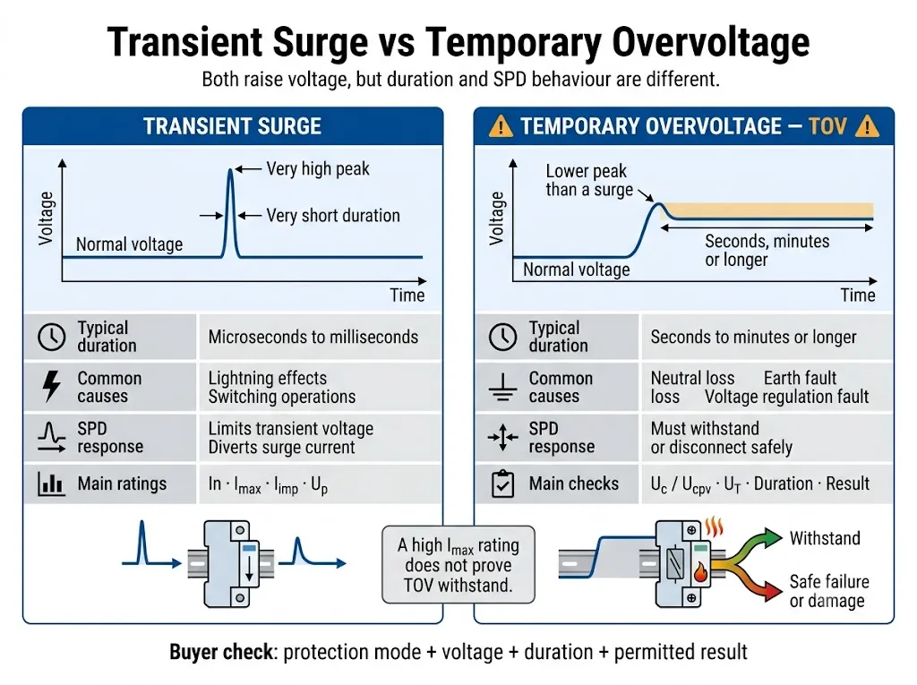
TOV and Surge Are Different Electrical Events
Both events raise voltage above its normal level. The important differences are duration, energy source and the way the SPD responds.
| Comparison | Transient surge | Temporary overvoltage |
|---|---|---|
| Nature | A short voltage or current impulse with a high peak. | An abnormal AC RMS or DC voltage that remains present. |
| Possible causes | Lightning effects, switching and inductive load interruption. | Neutral loss, earth faults, poor regulation, wrong supply voltage or source faults. |
| SPD function | Limits transient voltage and diverts impulse current. | Must remain stable or enter the declared controlled end-of-life condition. |
| Main ratings | In, Imax, Iimp and Up. | Uc or Ucpv, UT, protection mode, duration and result. |
| Main risk | Excessive impulse energy or accumulated surge stress. | Continuous conduction, heating, thermal runaway or fault-current follow-through. |
The applicable standard and product documentation determine the exact TOV test duration. Do not apply one universal time threshold to every system or SPD.
Four Fields Are Needed to Understand a TOV Rating
Statements such as “high TOV resistance” or “TOV-proof SPD” are not complete engineering data. Buyers need four specific fields.
| Required field | What it means | Procurement impact |
|---|---|---|
| Protection mode | The two conductors across which the abnormal voltage is applied. | L-N, L-PE and N-PE paths can experience different fault voltages. |
| Applied voltage | The specified AC RMS or DC TOV test voltage, often identified as UT. | Compare it with the credible abnormal voltage in the actual system. |
| Duration | How long the abnormal voltage is applied during the stated condition. | An SPD may withstand one voltage briefly but disconnect during a longer exposure. |
| Result | The required behaviour after or during the test. | Determine whether the SPD remains functional, disconnects or requires replacement. |
Uc, Ucpv and UT Do Not Mean the Same Thing
Uc is the maximum continuous operating voltage that may be continuously applied to the stated SPD protection mode. Ucpv is the corresponding parameter used for photovoltaic SPDs.[1][2][6]
UT describes behaviour during a specified temporary abnormal-voltage condition. Uc or Ucpv and UT are related, but one cannot replace the other.
| Parameter | Question answered | Approval risk |
|---|---|---|
| Un or Uo | What is the nominal system or phase-to-neutral voltage? | It is a starting point, not the final SPD voltage-selection value. |
| Uc | Can the SPD remain connected continuously at this voltage? | A value that is too low can increase leakage, heating and early disconnection. |
| Ucpv | Can the PV SPD remain connected at the calculated maximum array voltage? | Normal inverter operating voltage alone is not enough. |
| UT | What happens under the stated abnormal voltage and duration? | A voltage value without duration and result is incomplete. |
| Up | What voltage protection level is declared during the specified surge test? | A higher Uc does not automatically provide the most suitable protection coordination. |
Why Can a Low Uc Cause Failure?
Most voltage-limiting AC power SPDs use one or more metal-oxide varistors. Under normal voltage, an MOV carries only a small leakage current.
When the applied voltage rises beyond the component’s stable operating range, MOV current can increase sharply. If the abnormal voltage remains, electrical energy is converted into heat rather than being handled as one short surge impulse.[9]
Is a Higher Uc Always Better?
No. A higher Uc can increase continuous-voltage margin, but the selected SPD must still provide a suitable Up, protection mode and coordination with the equipment being protected.
The correct choice is not simply the highest available Uc. It is a rating that safely covers the real maximum operating voltage and credible fault conditions while meeting the required protection level.[3]
How Can TOV Make an SPD Heat, Disconnect or Burn?
The exact response depends on SPD technology, internal construction and the system fault. A common MOV-based failure sequence is shown below.
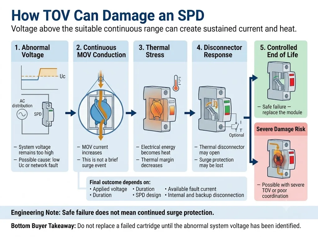
- The applied voltage exceeds the suitable continuous range. This may result from a low Uc selection or an abnormal system condition.
- The voltage-limiting component conducts continuously. The SPD is drawing power-frequency or DC current instead of handling one short impulse.
- Internal temperature rises. Continued energy input reduces the remaining thermal margin.
- The thermal disconnector may open. A controlled disconnection can isolate the stressed component and change the status indicator.
- Severe damage remains possible. A severe TOV, high available fault current or inadequate disconnection can enlarge the failure.
NIST-hosted TOV research found that SPD responses under sustained abnormal voltage can range from no damage to complete destruction. The paper identifies maximum continuous operating voltage and disconnector response as important factors in TOV susceptibility.[9]
TOV Must Be Checked for Each Protection Mode
A multipole SPD is not exposed to one single voltage. Each protection element sees the voltage between the two conductors connected to that protection path.
| Protection mode | Normal selection question | TOV risk to confirm |
|---|---|---|
| L-N | What is the maximum continuous phase-to-neutral voltage? | Neutral loss, poor neutral connection and load imbalance. |
| L-PE | What voltage can appear between the phase conductor and earth? | Earth faults, neutral displacement and earthing-system behaviour. |
| N-PE | Which N-PE protection technology and rating are used? | Temporary neutral-to-earth voltage during certain earth-fault conditions. |
| DC +/− | What is the maximum pole-to-pole DC voltage? | Charging voltage, regulation faults and incorrect circuit configuration. |
| DC pole-PE | How is the DC system referenced to earth? | An earth fault can shift the voltage across a pole-to-earth protection path. |
Why Neutral Loss Is a Critical AC TOV Scenario
In a healthy 230/400 V three-phase four-wire system, an L-N protection path normally sees approximately 230 V.
If the neutral conductor opens or develops high impedance, the neutral point is no longer stable. With unbalanced single-phase loads, some L-N voltages can fall while another rises substantially and may approach the 400 V line-to-line voltage.[4][9]
Healthy Supply Versus Neutral-Loss Condition
A 275 V Uc SPD may be suitable for a stable 230 V L-N circuit when the complete system and product requirements are satisfied.
If neutral loss causes the same protection path to experience a much higher sustained voltage, the SPD may begin conducting continuously. Whether it withstands, disconnects safely or suffers damage must be confirmed from the exact model’s TOV data.
This example does not prove that every neutral-loss event produces exactly 400 V. The actual voltage depends on the connected loads, network arrangement and fault condition.
Earth Faults and Earthing Arrangement
TN-S, TN-C-S, TT and IT systems can place different temporary voltages across L-N, L-PE and N-PE protection paths. The actual stress depends on the installation arrangement and fault condition.[3][4]
This is especially important when comparing 4+0 and 3+1 circuits. The L-N modules and the N-PE element perform different functions and should not be assumed to have identical TOV behaviour.
Generators, Transformers and Unstable Grids
Generator regulation faults, transformer-tap errors, load rejection, ferroresonance and poor utility regulation can create sustained abnormal voltage.
For these projects, request measured voltage records or the design voltage tolerance. Nominal voltage alone is not sufficient for final Uc approval.
Installation-level requirements and system-specific TOV conditions should be checked against the applicable edition of IEC 60364 and the local electrical code. The related IEC 60364-5-534 SPD installation guide explains the wider installation checks.
How to Read a Real TOV Datasheet Entry
The following example uses values published in a third-party manufacturer’s technical guide. It explains the reading method only. It is not a recommendation for a LEEYEE model and must not be transferred to another product without verification.[10]
| Published entry | Correct interpretation | Wrong assumption to avoid |
|---|---|---|
| Uc 275 V | The declared maximum continuous operating voltage for the stated protection mode. | The product can operate continuously at every voltage below its highest UT value. |
| UT 337 V / 5 s | A short-duration TOV condition with the outcome stated in the same product documentation. | 337 V is another continuous operating-voltage rating. |
| UT 442 V / 120 min | A longer-duration condition associated with a declared safe-failure result. | The SPD continues protecting normally for two hours at 442 V. |
| Separate N-PE value | A TOV condition specifically stated for the N-PE protection element. | The same value automatically applies to L-N and L-PE elements. |
What Should Be Verified on a LEEYEE Model?
Do not assume that a third-party example represents a LEEYEE product. Request the exact LEEYEE model datasheet, connection diagram and applicable test or certificate scope for project confirmation.
Model-Specific Evidence to Request
- Exact product and cartridge label
- Uc or Ucpv for the stated protection mode
- UT voltage, duration and declared result
- Visual status-window operation
- Remote signalling contact information
- Internal and external disconnection requirements
- Isccr or ISCPV rating where applicable
- Backup fuse or MCB requirements
- Installation and wiring instructions
- Model-specific report or certificate scope
- OEM label and packaging approval drawing
- Sample inspection and approval record
Evidence should be reviewed at exact-model level. A certificate, report or datasheet for one voltage version or pole configuration must not be assumed to cover another.
Do AC TOV Conclusions Apply Directly to DC or PV SPDs?
No. General DC and solar PV circuits require separate voltage calculations, protection modes and product standards.
IEC 61643-41:2025 covers SPDs connected to general DC low-voltage power circuits. PV SPDs remain within IEC 61643-31, with selection principles addressed by IEC 61643-32.[5][6][7]
Use the separate DC and PV SPD Ucpv selection guide for the complete PV voltage-selection process.
SPD TOV Verification Workflow for OEM Approval
Confirm the electrical system before approving the SPD. The workflow below keeps system data, product ratings and approval documents connected.
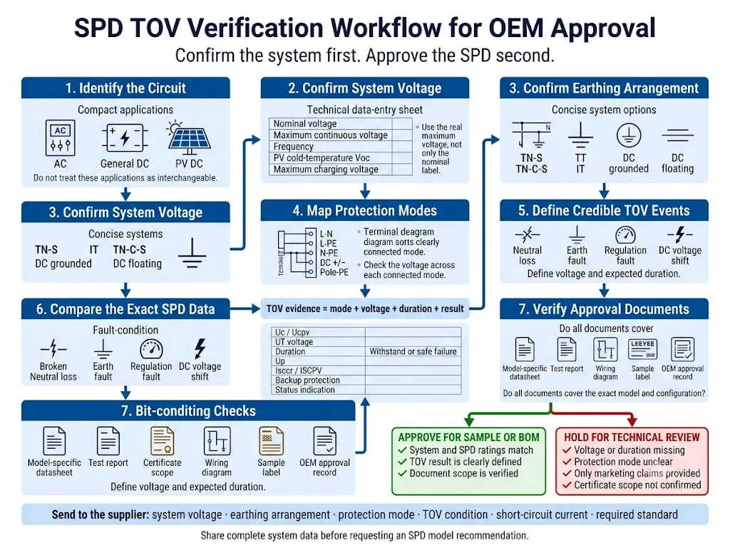
- Identify the circuit. Separate AC mains, general DC and solar PV applications. Similar housings do not make the products interchangeable.
- Confirm the real maximum operating voltage. Include supply tolerance, generator or transformer behaviour, charging voltage or PV cold-temperature voltage.
- Confirm the earthing arrangement. Record TN-S, TN-C-S, TT, IT or the relevant DC grounding method.
- Map every protection mode. Check L-N, L-PE, N-PE, pole-to-pole and pole-to-earth paths as applicable.
- Define credible TOV events. Review neutral loss, earth faults, regulation faults and source-specific abnormal conditions.
- Compare the complete SPD data. Review Uc or Ucpv, UT, duration, result, Up, short-circuit rating and disconnection arrangement.
- Verify approval-document scope. Confirm that the datasheet, report and certificate apply to the exact voltage version, pole configuration and model ordered.
Information to Send Before Requesting a Model Recommendation
- Nominal system voltage
- Maximum continuous voltage
- AC, general DC or PV application
- System frequency where applicable
- Earthing or grounding arrangement
- Required protection modes
- Neutral-loss or earth-fault scenario
- Uc or Ucpv under consideration
- Required TOV voltage and duration
- Required withstand or safe-failure result
- Prospective short-circuit current
- Backup fuse or MCB information
- Required standard or certificate
- Remote signalling requirement
- Quantity and installation position
- OEM label or packaging requirement
Confirm TOV Data Before Approving the SPD Model
Send the system voltage, earthing arrangement, protection modes and credible abnormal-voltage conditions. LEEYEE can help identify which Uc, Ucpv and TOV data should be verified before sample or BOM approval.
CNSPD is LEEYEE’s surge protection-focused platform for global technical buyers. Built to Protect. Trusted to Last.
Share Your System Details for ReviewWhat Should Be Checked After a Suspected TOV Event?
Do not install a replacement cartridge before identifying the original abnormal voltage. A new SPD may fail again if the system fault remains.
- Isolate the circuit according to the site’s electrical-safety procedure.
- Record the SPD indicator, remote alarm and complete product label.
- Measure L-N, L-L, L-PE, N-PE or DC pole voltages as applicable.
- Check neutral continuity, earthing and the current single-line diagram.
- Inspect the cartridge, base, conductors, terminals and backup protection.
- Review generator, transformer, inverter, relay and utility-event records.
- Confirm the replacement Uc, Ucpv, TOV data and protection configuration.
For a wider diagnostic process, use the related SPD failure causes guide.
Frequently Asked Questions About SPD TOV Withstand
Can an SPD protect equipment against a temporary overvoltage?
An SPD is primarily intended to limit transient overvoltages. It does not normally regulate or remove a sustained abnormal system voltage. During a TOV, it may remain stable or enter its declared controlled end-of-life condition.
Can TOV make an SPD burn?
Yes. Sustained conduction can cause heating, thermal runaway, disconnection or severe damage. The result depends on voltage, duration, SPD design, available fault current and protective-device coordination.
Does a larger Imax improve TOV withstand?
Not necessarily. Imax is an impulse-current parameter. TOV suitability depends on continuous operating voltage, protection mode, defined TOV behaviour and disconnection design.
Does a higher Uc prevent every TOV failure?
No. A higher Uc can increase continuous-voltage margin, but duration, protection mode, SPD technology and disconnection behaviour still affect the result.
Can neutral loss damage a 275 V or 320 V SPD?
It can. Neutral displacement in a three-phase four-wire system can raise the voltage across an L-N protection path well above normal. The outcome depends on the actual voltage, duration and model-specific TOV behaviour.
What does safe failure mean?
It means that controlled disconnection or end of life may be permitted under the stated test condition. It does not mean that the module continues to provide surge protection.
Is Ucpv the same as a PV system’s nominal voltage?
No. Ucpv is the maximum continuous operating voltage declared for the PV SPD. It must be checked against the maximum voltage calculated for the actual PV array and protection configuration.
Which TOV documents should an OEM buyer request?
Request the exact-model datasheet, protection-mode diagram, Uc or Ucpv, UT voltage, duration, result definition, short-circuit rating, backup-protection requirements, installation instructions and certificate scope.
References
- International Electrotechnical Commission, IEC 61643-01:2024 — Low-voltage surge protective devices — Part 01: General requirements and test methods. Official IEC publication page.
- International Electrotechnical Commission, IEC 61643-11:2025 — Low-voltage surge protective devices — Part 11: Surge protective devices connected to AC low-voltage power systems — Requirements and test methods. Official IEC publication page.
- International Electrotechnical Commission, IEC 61643-12:2020 — Low-voltage surge protective devices — Part 12: Surge protective devices connected to low-voltage power systems — Selection and application principles. Official IEC publication page.
- International Electrotechnical Commission, IEC 60364-4-44:2024 — Low-voltage electrical installations — Part 4-44: Protection for safety — Protection against voltage disturbances and electromagnetic disturbances. Official IEC publication page.
- International Electrotechnical Commission, IEC 61643-41:2025 — Low-voltage surge protective devices — Part 41: Surge protective devices connected to DC low-voltage power systems — Requirements and test methods. Official IEC publication page.
- International Electrotechnical Commission, IEC 61643-31:2018 and Corrigendum 1:2022 — Requirements and test methods for SPDs for photovoltaic installations. Official IEC publication page.
- International Electrotechnical Commission, IEC 61643-32:2017 and Corrigendum 1:2019 — Surge protective devices connected to the DC side of photovoltaic installations — Selection and application principles. Official IEC publication page.
- International Electrotechnical Commission, IEC 60364-7-712:2025 — Low-voltage electrical installations — Solar photovoltaic power-supply installations. Official IEC publication page.
- D. Kladar, F. Martzloff and D. Nastasi, TOV Effects on Surge-Protective Devices, Eaton Electrical and EPRI Solutions, hosted by the U.S. National Institute of Standards and Technology. NIST-hosted technical paper.
- ABB Furse, ESP Type 1 and Type 2 Surge Protection Series Product Guide, including model-specific Uc, UT, withstand and safe-failure data. Official ABB technical guide.
