
Este guía de diagrama de cableado de protector contra sobretensiones monofásico explica cómo los fabricantes de paneles deben conectar SPDs 1P+N y 2P, identificar terminales L, N y PE, coordinar la protección de respaldo, posicionar el SPD en relación con un RCD y revisar los arreglos de puesta a tierra TT o TN-S.
Índice
¿Cómo se conecta un SPD en un cuadro de distribución monofásico?
En un cuadro de distribución monofásico típico, el SPD está conectado en paralelo. En conexión L se toma de la fuente o barra de distribución entrante y se enruta a través del MCB o fuse de respaldo especificado cuando es necesario. El conexión N va al punto neutro designado o barra neutra. La conexión PE va directamente a la barra de tierra utilizando el conductor práctico más corto.
El diagrama exacto cambia con la topología interna del SPD, el sistema de aterrizaje y la disposición del RCD. Un SPD 1P+N y un SPD 2P no deben tratarse como intercambiables automáticamente.
Estos diagramas explican la lógica típica de diseño de panel. La instalación final, tamaño del conductor, protección de respaldo y conexiones de terminales deben seguir las instrucciones del fabricante del SPD seleccionado, el dibujo del panel aprobado, las normas aplicables y las reglas eléctricas locales.
Cómo leer un diagrama de cableado de SPD monofásico
Un diagrama de cableado de SPD en una fase única debe mostrar dos caminos eléctricos diferentes: el camino de corriente de carga normal y el camino de desvío de corriente de sobretensión.
Durante el funcionamiento normal, la corriente fluye a través del interruptor principal, RCD o RCBO, interruptores de salida y cargas. Normalmente no pasa a través del SPD como si el SPD fuera un interruptor automático conectado en serie.
Durante un sobretensión transitoria, el SPD crea temporalmente un camino de impedancia más bajo y desvía la corriente de sobretensión a través del modo de protección correspondiente L-N, L-PE o N-PE.
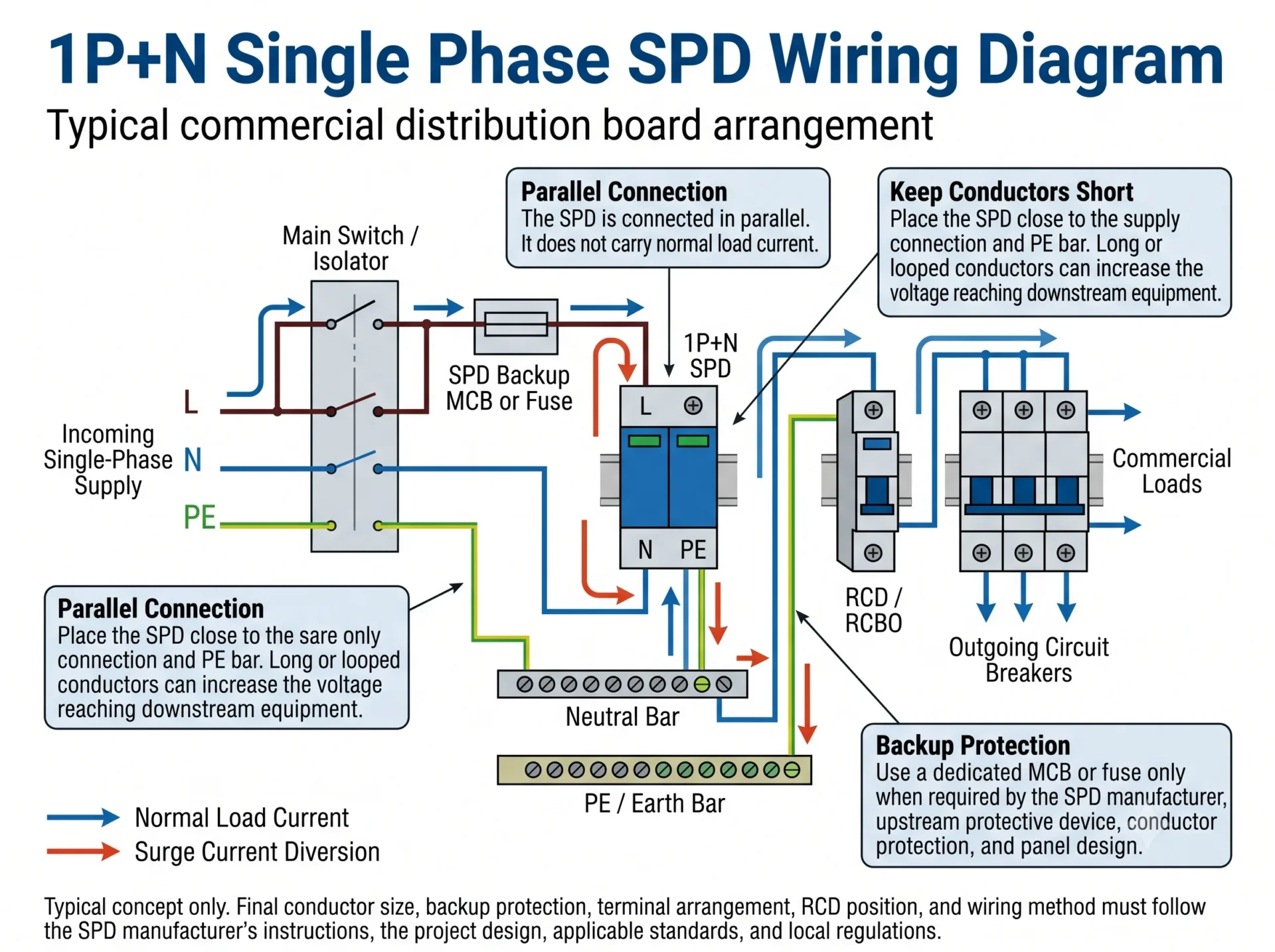
Punto de diseño del panel: Un esquema puede ser eléctricamente correcto, pero aun así ofrecer una protección real deficiente si el SPD se monta lejos del punto de alimentación o de la barra PE.
Diagrama de cableado de SPD monofásico 1P+N
Un SPD 1P+N típico combina una función de protección relacionada con la fase con una función de protección dedicada relacionada con el neutro. Una disposición común utiliza una vía de limitación de tensión L-N y una vía de conmutación de tensión N-PE.
Secuencia típica de conexión 1P+N
- Tome la rama del SPD desde la conexión de alimentación de entrada o la barra colectora.
- Dirija la rama activa a través del MCB o fusible de respaldo especificado cuando se requiera protección de respaldo independiente.
- Conecte el terminal L a la rama activa mostrada en el diagrama del producto.
- Conecte el terminal N al punto de conexión de neutro designado.
- Conecte el terminal PE o la conexión a tierra directamente a la barra PE.
- Mantenga cortos los tres trayectos de conexión y evite bucles innecesarios.
Importante: La designación 1P+N no demuestra que todos los fabricantes utilicen la misma disposición de MOV, GDT, chispero o terminales. Compruebe el símbolo de circuito impreso en el producto o mostrado en su documentación técnica.
Diagrama de cableado de SPD monofásico 2P
Un SPD 2P suele proporcionar dos polos protegidos para los conductores activo y neutro. En una disposición común, L y N tienen cada uno una vía de protección hacia PE. Otros productos 2P pueden utilizar un circuito interno diferente.
Externamente, el conductor activo se conecta al polo L, el conductor neutro se conecta al polo N y la conexión a tierra del SPD se conecta a la barra PE. La carga permanece conectada a través del circuito de distribución normal en lugar de a través del SPD.
| Conductor o conexión | Conexión típica | Qué debe comprobarse |
|---|---|---|
| L | Alimentación de entrada o barra colectora hasta el polo activo del SPD. | Uc, protección de respaldo y marcaje del terminal. |
| N | Punto de conexión de neutro o barra de neutro hasta el polo neutro del SPD. | Si el polo neutro está protegido hacia PE o mediante otro modo interno. |
| PE | Terminal de puesta a tierra SPD hacia la barra PE. | Trayectoria del conductor corta y directa. |
| Circuito de carga | Continúa a través del interruptor principal normal, el RCD y los dispositivos de protección de salida. | El SPD permanece conectado en paralelo. |
Una envolvente 2P no demuestra una topología interna 2+0. Revise los modos de protección reales L-N, L-PE y N-PE antes de sustituir un dispositivo 1P+N o aprobar un modelo OEM.
1P+N vs 2P SPD: por qué el número de polos por sí solo no es suficiente
Los términos 1P+N, 2P, 1+1 y 2+0 describen ideas relacionadas, pero no siempre describen el mismo circuito interno de protección. La cantidad física de módulos no basta para identificar los modos de protección.
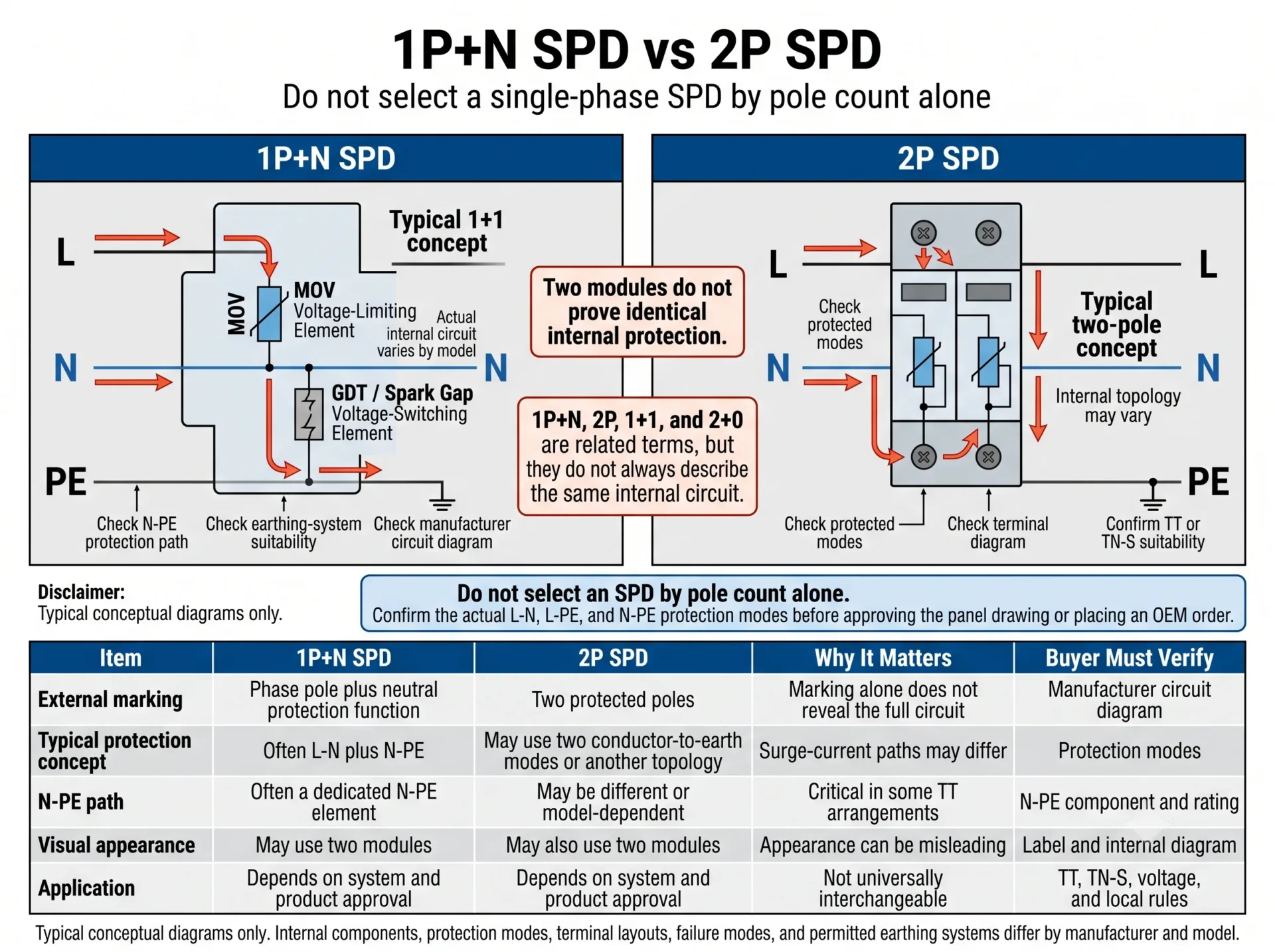
| Marcado | Lo que puede describir | Por qué es importante | Qué verificar |
|---|---|---|---|
| 1P+N | Protección de fase más una función de protección relacionada con el neutro. | La trayectoria N-PE puede utilizar un componente distinto de la trayectoria de fase. | Circuito interno, elemento N-PE, Uc y aptitud para el sistema de puesta a tierra. |
| 2P | Dos polos protegidos o dos canales. | No equivale automáticamente a un dispositivo 1P+N. | Modos protegidos, diagrama de terminales y aplicación aprobada. |
| 1+1 | A menudo un modo limitador de tensión más un modo conmutador de tensión. | La trayectoria de corriente de sobretensión y el comportamiento ante fallos pueden diferir. | Componentes reales y sistema de puesta a tierra permitido. |
| 2+0 | A menudo dos modos de limitación de tensión de conductor a tierra. | No es un sustituto universal de una configuración 1+1. | Comportamiento ante sobretensiones temporales, topología y requisitos locales. |
| Dos módulos | Solo apariencia física. | Los SPD de aspecto similar pueden usar circuitos diferentes. | Diagrama lateral, hoja de datos y confirmación del fabricante. |
¿Dónde deben conectarse L, N y PE?
L — Conductor vivo
Conecte el conductor vivo desde el punto de alimentación designado al terminal L del SPD. Cuando sea necesario, dirija esta derivación a través del MCB de respaldo coordinado o del fusible.
N — Conductor neutro
Conecte el terminal neutro al punto neutro designado o a la barra colectora de neutro. Compruebe si el producto utiliza una configuración de protección L-N, N-PE o combinada.
PE — Tierra de protección
Conecte la trayectoria a tierra del SPD directamente a la barra de PE. El conductor debe ser corto, recto y estar libre de bucles innecesarios.
Separación entre N y PE
No cree una unión neutro-tierra no autorizada dentro del cuadro de distribución. Las relaciones entre el neutro y el PE están determinadas por el sistema de puesta a tierra y el diseño aprobado del cuadro.
¿Necesita un SPD monofásico un MCB o fusible dedicado?
Se requiere un interruptor automático (MCB) o fusible independiente cuando el fabricante del SPD lo especifique, cuando el dispositivo de protección anterior supere el máximo permitido, cuando los conductores de derivación necesiten una protección independiente o cuando el diseño del cuadro requiera un medio de desconexión dedicado.
No seleccione el MCB de respaldo basándose directamente en el valor de In o Imax del SPD. In e Imax describen el rendimiento frente a sobretensiones, no la capacidad nominal del dispositivo de sobreintensidad normal.
Lea la hoja de datos y las instrucciones de instalación del SPD seleccionado.
Determine si la protección de alimentación existente ya cumple con el límite de coordinación del fabricante.
El SPD y la disposición de protección deben ser adecuados para el nivel de fallo en el punto de instalación.
La sección transversal del conductor, su recorrido y el método de instalación influyen en la decisión de protección.
Un MCB independiente puede facilitar el aislamiento y la sustitución, pero la disposición final debe coincidir con la norma del cuadro.
¿Debería instalarse el SPD antes o después del RCD?
En muchos cuadros monofásicos comerciales, el SPD se instala aguas arriba de los circuitos finales protegidos por RCD o RCBO. Esto ayuda a evitar que toda la trayectoria de la corriente de sobretensión pase a través de cada dispositivo de corriente residual aguas abajo.
Cuando se utiliza un RCD como interruptor principal, especialmente en un sistema TT, la posición final del SPD debe revisarse junto con el tipo de RCD, la inmunidad a corrientes de sobretensión, la disposición del neutro y la topología de SPD seleccionada.
| Disposición del cuadro | Posición típica del SPD | Principal preocupación de diseño |
|---|---|---|
| Circuitos finales con RCBO aguas abajo | Normalmente aguas arriba de los RCBO de los circuitos finales. | Evite dirigir la trayectoria de la corriente de sobretensión a través de todos los dispositivos de corriente residual aguas abajo. |
| RCD de entrada principal | Específico del proyecto. | Inmunidad a sobretensiones del RCD, selectividad, topología del SPD y sistema de puesta a tierra. |
| SPD aguas abajo de un RCD | Solo cuando el RCD y el SPD están adecuadamente coordinados. | Posibles disparos molestos y resistencia a la corriente de impulso del RCD. |
| Sistema TT | Depende de la arquitectura del RCD y del tipo de conexión seleccionada. | Trayectoria de protección N-PE, coordinación de RCD y normas de cableado locales. |
| TN-S con RCD aguas abajo | Normalmente aguas arriba de los circuitos protegidos por RCD aguas abajo. | Ruta PE corta, topología correcta y diagrama del fabricante. |
Regla práctica: Primero identifique si el RCD es el dispositivo de entrada principal o un dispositivo de circuito final aguas abajo. Luego revise el sistema de puesta a tierra y los modos de protección del SPD antes de fijar la posición del SPD.
Cableado de SPD monofásico en sistemas TT vs TN-S
Tanto los sistemas TT como los TN-S mantienen el neutro y la tierra de protección separados en el cuadro aguas abajo, pero el origen de la trayectoria de tierra de protección es diferente. Esa diferencia influye en la trayectoria de sobretensión, la protección N-PE y la coordinación de los RCD.
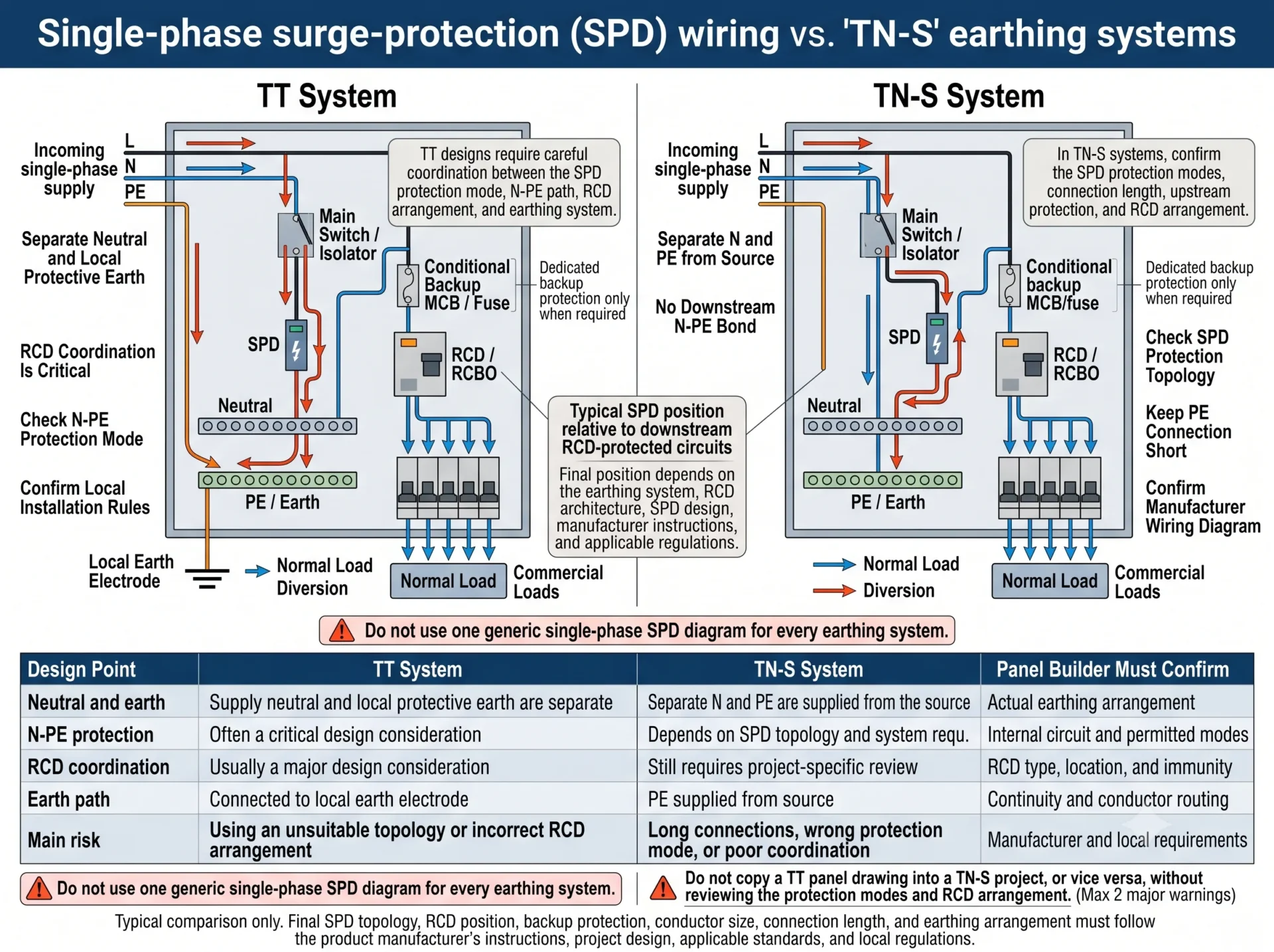
| Punto de diseño | Sistema TT | Sistema TN-S | El fabricante del cuadro debe confirmar |
|---|---|---|---|
| Neutro y tierra | El neutro de alimentación y el sistema de puesta a tierra local están separados. | Se suministran conductores N y PE separados desde la fuente. | Disposición real de puesta a tierra y diagrama unifilar aprobado. |
| protección N-PE | A menudo una parte crítica de la topología seleccionada. | Depende del producto y del diseño del sistema. | Circuito interno y modos de protección permitidos. |
| Coordinación del RCD | Suele ser una consideración de diseño importante. | Sigue siendo necesario cuando hay instalados dispositivos de corriente residual (RCD) principales o secundarios. | Tipo de RCD, posición, inmunidad y recorrido del neutro. |
| Camino de la corriente a tierra | Desviada hacia el sistema de protección de tierra (PE) local y el electrodo de tierra. | Desviada hacia el conductor de protección (PE) suministrado. | Continuidad, longitud del conductor y ubicación de la barra de PE. |
| Principal riesgo de error | Topología N-PE incorrecta o mala coordinación del RCD. | Modo de protección incorrecto o longitud excesiva del conductor. | Compatibilidad del producto y del proyecto. |
Por qué la longitud del conductor SPD cambia el nivel de protección instalado
El valor Up en una hoja de datos se mide en condiciones de prueba definidas. En un cuadro de distribución real, los conductores de conexión de L, N y PE añaden tensión inductiva durante una sobretensión rápida.
Esfuerzo aproximado del equipo = Up del SPD + tensión añadida por los conductores de conexión.
Por eso la disposición del panel es importante. Un SPD bien seleccionado instalado con conductores largos o en bucle puede proporcionar una protección real peor de lo esperado.
- Coloque el SPD cerca de la conexión de alimentación de entrada.
- Mantenga la conexión PE corta y directa.
- Evite grandes bucles y curvas innecesarias en los conductores.
- No coloque el SPD en el extremo remoto del riel DIN solo por conveniencia.
- Utilice el cableado en V o pasante solo cuando los terminales y las instrucciones del fabricante lo permitan.
- Cuando las conexiones cortas sean imposibles, revise la protección contra sobretensiones secundaria coordinada.
Errores comunes en el cableado de SPD monofásico
La corriente de carga normal no debe pasar a través del SPD.
Dos módulos no prueban que dos SPD utilicen la misma topología interna.
La puesta a tierra y la coordinación del RCD deben revisarse por separado.
Imax no determina directamente la clasificación del MCB de respaldo.
Una ruta de tierra larga añade tensión durante un transitorio rápido.
El neutro y el PE deben seguir la disposición de puesta a tierra aprobada.
No copie "siempre antes" o "siempre después" en todos los proyectos.
El SPD y la protección de respaldo deben coincidir con el nivel de falta de la instalación.
Lista de verificación de SPD monofásico para fabricantes de paneles
Confirme estos detalles antes de publicar un plano o realizar un pedido OEM:
Resumen del cableado de SPD monofásico
- Conecte el SPD en paralelo, no en serie con la carga.
- Conecte L desde la alimentación o barra colectora, N al punto neutro designado y PE directamente a la barra de tierra.
- Confirme si el producto es verdaderamente 1P+N, 2P, 1+1 o 2+0 a partir de su diagrama de circuito interno.
- Seleccione el MCB o fusible de respaldo a partir de los datos de coordinación del fabricante, la protección de cabecera y las condiciones de corriente de falta.
- En muchos cuadros, el SPD se sitúa aguas arriba de los circuitos protegidos por RCD, pero las disposiciones con RCD general y sistema TT requieren una revisión adicional.
- Mantenga las conexiones L, N y PE cortas porque la inductancia del conductor aumenta la tensión que llega al equipo.
¿Necesita ayuda para confirmar un modelo de SPD monofásico?
Envíenos la tensión de su sistema, la disposición de puesta a tierra, el diagrama del cuadro, la protección de cabecera y la posición del RCD. LEEYEE puede ayudarle a confirmar una configuración de SPD adecuada para cuadros de distribución comercial, paneles OEM y pedidos al por mayor.
Preguntas frecuentes
¿Cómo se conecta un SPD en un cuadro de distribución monofásico?
El SPD se conecta normalmente en paralelo. L se conecta desde la alimentación o la barra colectora a través de la protección de respaldo cuando es necesario, N se conecta al punto neutro designado y PE se conecta directamente a la barra de tierra.
¿Está un SPD monofásico conectado en serie o en paralelo?
Se conecta normalmente en paralelo. La corriente de carga normal no pasa a través del SPD.
¿Cuál es la diferencia entre el cableado SPD 1P+N y 2P?
Un SPD 1P+N a menudo utiliza una función de protección específica para el neutro, mientras que un SPD 2P proporciona dos polos o canales protegidos. Los modos internos exactos deben verificarse en el esquema del producto.
¿Puede un SPD de 2 polos reemplazar a un SPD de 1 polo + neutro?
No automáticamente. Confirme primero los modos de protección L-N, L-PE y N-PE, los valores nominales de Uc, la idoneidad del sistema de puesta a tierra y la protección de respaldo.
¿Un SPD monofásico necesita un MCB separado?
Depende del valor máximo de protección de respaldo del fabricante, el dispositivo aguas arriba, la protección del conductor de derivación y la corriente de cortocircuito en el punto de instalación.
¿Debería instalarse el SPD antes o después del RCD?
Normalmente se instala aguas arriba de los circuitos finales protegidos por RCD o RCBO. Los sistemas TT y el RCD de entrada principal requieren una coordinación específica del proyecto.
¿Dónde debe conectarse el cable de tierra SPD?
Conéctelo directamente a la barra de PE o de tierra designada con el recorrido de conductor más corto posible.
¿Pueden los sistemas TT y TN-S utilizar el mismo diagrama de cableado de SPD?
No deben considerarse automáticamente idénticos. La ruta de protección N-PE, la ruta de la corriente de tierra y la coordinación del RCD deben revisarse para el sistema real.
¿Qué tan cortos deben ser los conductores de conexión SPD?
Manténgalos lo más cortos y directos posible. El recorrido completo, incluidos los dobleces y la conexión PE, afecta el nivel de protección instalado.
¿Determina Imax la clasificación del MCB de respaldo?
No. Imax es un parámetro de corriente de sobretensión. La protección de respaldo se selecciona a partir de los datos de coordinación del fabricante, la protección aguas arriba, la protección del conductor y las condiciones de corriente de falla.
Referencias técnicas
- IEC 61643-11 — Dispositivos de protección contra sobretensiones de baja tensión para sistemas de potencia de CA: requisitos y métodos de prueba.
- IEC 61643-12 — Dispositivos de protección contra sobretensiones de baja tensión: principios de selección y aplicación.
- IEC 60364-5-53 — Selección e instalación de equipos eléctricos: aislamiento, conmutación y control.
- Instrucciones de instalación del fabricante y datos de coordinación para el modelo de SPD seleccionado.
- Normativas nacionales de cableado aplicables y documentación de proyecto aprobada.
