
Water treatment plant surge protection cannot stop at one AC surge protective device installed in the main switchboard. Transient overvoltage can also enter through pump feeders, 24 V DC control power, outdoor transmitters, 4–20 mA loops, RS485 or Modbus cables, Ethernet links and remote pumping-station wiring.
This guide explains how to identify those entry paths, protect each electrical interface and prepare a complete SPD list for a water or wastewater treatment project. It is written for control-panel manufacturers, municipal contractors, automation integrators, engineering reviewers, maintenance teams and B2B project buyers.
Scope clarification: This page covers electrical transient overvoltage protection for power, control, instrumentation and communication circuits. It does not cover hydraulic pressure surge, water hammer analysis or surge-vessel sizing.
Índice
Respuesta Rápida
A complete water treatment plant surge protection system protects every external conductive path that can carry a transient into critical equipment. AC power, DC control power, analogue signals and communication circuits should be assessed separately because they use different voltages, currents, wiring methods and signal characteristics.[3][6][10]
| Plant area | Exposed interface | Initial engineering direction |
|---|---|---|
| Main switchboard | Three-phase AC supply | Assess Type 1, Type 1+2 or Type 2 duty according to the lightning concept, supply arrangement, earthing system and project rules. |
| Process distribution board | AC feeder circuits | Coordinate downstream protection with the upstream SPD, cable route and equipment withstand requirements. |
| Pump or VFD panel | AC input, control power and field wiring | Protect the panel power entry, then review external sensors, control conductors and communication ports separately. |
| PLC or remote I/O | AC/DC power, I/O and data | Treat power, analogue, digital and communication terminals as different protection interfaces. |
| Outdoor instruments | 4–20 mA, HART, pulse or digital signal | Match the SPD to loop voltage, wire count, current, resistance, leakage, bandwidth and installation environment. |
| Remote station or inter-building link | RS485, Modbus, Ethernet, telemetry or antenna cable | Assess protection at each exposed equipment boundary and coordinate it with shielding and equipotential bonding. |
One water treatment plant can require several SPD categories. The correct list is built from the real power, control and communication architecture, not from the plant name alone.
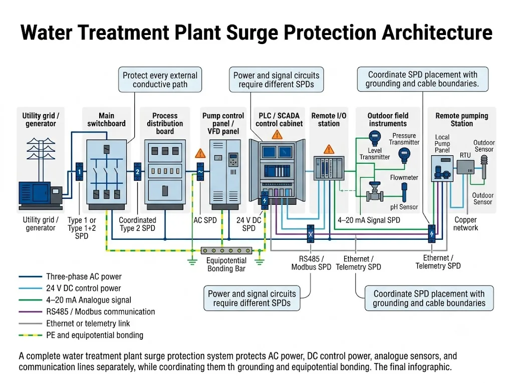
Start with the Plant Architecture, Not with One SPD Model
The first design task is to map how power and information move through the facility. A typical water or wastewater treatment plant may contain a utility service, generator, automatic transfer switch, main switchboard, motor-control centre, pump panels, VFDs, PLC cabinets, SCADA equipment, remote I/O, dosing systems, outdoor instruments and remote pumping stations.
Each conductor crossing from an exposed area into a protected cabinet can become a surge entry path. IEC 62305-4 addresses surge protection measures for electrical and electronic systems within structures, including coordinated protection at relevant boundaries.[3]
Map every equipment location
Show the main building, process areas, pumping stations, outdoor basins, remote cabinets, telemetry points and control room.
Map every conductive route
Include AC feeders, 24 V DC power, analogue loops, DI/DO, RS485, Ethernet copper, antenna coax, cable shields and PE conductors.
Mark exposed boundaries
Identify outdoor runs, inter-building cables, overhead sections, remote stations and every point where a field cable enters a cabinet.
Record connected equipment
List the power supply, PLC module, transmitter, gateway, VFD, RTU or network port connected at each end.
Significado para el comprador: Send the supplier a single-line diagram, control schematic, I/O list and network drawing. A request that only says “SPD for a wastewater plant” does not contain enough information for reliable model confirmation.
Where Can Surges Enter a Water or Wastewater Facility?
Lightning is not the only source of transient overvoltage. Switching operations, inductive loads and temporary differences in potential between separated areas can also stress control and communication equipment. IEC 60364-4-44 addresses protection against voltage and electromagnetic disturbances in low-voltage installations.[4]
The “equipment at risk” column shows why protection cannot stop at the facility incomer.
| Entry path | Water-treatment example | Equipment at risk |
|---|---|---|
| Utility or generator supply | Main service, ATS or standby generator feeder | Switchgear, distribution boards, control supplies, PLCs and VFDs |
| Long pump feeder | Lift station, borehole pump or remote booster station | Pump panel, VFD input, control transformer and auxiliary circuits |
| Outdoor instrument cable | Level, pressure, flow, pH or conductivity transmitter | Transmitter, isolator, marshalling terminal and PLC analogue input |
| Serial communication cable | RS485 or Modbus between a control room and remote I/O | Communication cards, gateways, HMIs, meters and SCADA interfaces |
| Ethernet or telemetry copper | Outdoor switch, radio modem, RTU or inter-building network | Network switch, router, modem, server port and remote controller |
| Switching event | Contactor, motor, relay, solenoid or capacitor switching | Nearby electronics and circuits sharing power or reference conductors |
An SPD limits transient overvoltage. It does not correct sustained overvoltage, phase loss, harmonics, incorrect shielding, RS485 termination errors or every disturbance associated with a drive system.
How Should the Main Switchboard AC SPD Be Selected?
The main switchboard is normally the first internal AC protection boundary. The required SPD duty depends on whether partial lightning current can enter, how the supply reaches the facility, whether an external lightning protection system is present and which national or project requirements apply.[1][2][3]
Do not assume that every water treatment plant automatically requires a Type 1 SPD. Type 1 or Type 1+2 duty should be evaluated where lightning current may enter the installation. Type 2 may be appropriate where Type 1 duty is not required or has already been addressed at an upstream boundary. The final decision belongs to the project designer and applicable installation rules.[5][7][8]
Confirm these parameters before selecting the incoming SPD
- Voltaje del sistema: nominal voltage, maximum continuous operating voltage, frequency and normal voltage variation.
- Earthing arrangement: TN-S, TN-C-S, TT, IT, delta or another project-specific configuration.
- Protection modes: phase-to-neutral, phase-to-PE, neutral-to-PE or other modes required by the system.
- SPD duty: Type 1, Type 2 or combined Type 1+2, based on the installation boundary and risk concept.
- Uc and Up: continuous operating-voltage withstand and voltage protection level must suit the system and equipment-protection objective.
- Iimp, In and Imax: compare each value only within its defined test duty. A larger number alone does not prove better project suitability.
- Short-circuit conditions: prospective short-circuit current, SPD short-circuit performance, internal disconnector and external backup protection.
- Monitoring: visual status, replaceable modules and a potential-free remote contact where the maintenance system requires remote indication.
Do not select the SPD only by the largest kA value
A discharge-current rating does not confirm the correct Uc, Up, protection mode, earthing arrangement, short-circuit compatibility or installation position. IEC 61643-01 and IEC 61643-11 define wider performance, rating and safety requirements for low-voltage SPDs.[6][7]
IEC and North American Projects Use Different Approval Language
Do not translate IEC classifications directly into North American SPD Types. The standards, terminology, test information and permitted installation positions must be confirmed for the target market.
Procurement rule: Request the certificate or certification record for the exact proposed model. A certificate held by one series or configuration must not be assumed to cover every voltage, pole arrangement or accessory option.
Downstream Boards Must Be Coordinated with the Incoming SPD
A downstream process board or control cabinet may require another protection stage when it is remote from the incoming board, supplied by a long exposed cable, located in another building or connected to sensitive equipment.
Coordination is not determined by distance alone. The upstream and downstream SPD characteristics, connection arrangement, cable impedance, protection level and terminal-equipment withstand must be reviewed together. Follow the relevant application standard, product instructions and project design.[5][8][14]
Engineering meaning: Do not automatically repeat the same SPD in every cabinet. A second stage should provide useful coordinated protection rather than duplicate a model without an engineering reason.
What Protection Does a Pump Control or VFD Panel Need?
A pump panel can contain several independent surge entry paths: the AC feeder, an auxiliary AC circuit, a 24 V DC supply, level switches, analogue transmitters, remote-start conductors and RS485 or Ethernet communication.
The incoming power side is normally the first circuit to assess. A downstream AC SPD may be considered when the panel is remote, supplied by an exposed feeder or needs coordination with sensitive drive and control electronics. The actual arrangement must match the upstream SPD, panel voltage, earthing system and fault level.
Separate the VFD power path from its control interfaces
An AC SPD installed at the panel incomer does not automatically protect the drive’s analogue input, digital I/O, RS485 port or remote sensor cable.
The VFD output is a project-specific PWM circuit. Do not select an output-side protective component from a generic AC SPD table. Any device connected on that side must be approved against the drive, motor, cable and filter documentation.
Check every cable leaving the pump panel
- Level-switch or float-switch conductors;
- 4–20 mA pressure, flow or level feedback;
- Remote start, stop and alarm circuits;
- Valve position or actuator feedback;
- RS485 or Modbus connection to PLC, HMI or SCADA;
- Ethernet copper or telemetry modem connections;
- 24 V DC supply to outdoor instruments or remote I/O.
For deeper panel-level selection, see the VFD surge protection guide y el PLC I/O signal surge protection guide.
PLC and Remote I/O Require Interface-by-Interface Protection
A PLC cabinet is not protected as one object. Its power input, 24 V DC bus, analogue modules, digital modules and communication ports are electrically different interfaces.
AC power input
Match the AC SPD to the panel voltage, earthing arrangement, upstream stage, protection mode and available short-circuit current.
24 V DC control power
Use a DC power SPD selected for the real maximum DC voltage, current, polarity, source behaviour and fault conditions.[9]
E/S de PLC
Match the signal SPD to DI, DO, AI, AO, pulse, contact or transmitter-loop characteristics.
A remote I/O or RTU enclosure can be more exposed than the central control room. It may have a local AC feeder, 24 V DC power, several sensor cables, RS485, Ethernet and an external antenna. Treat the enclosure as its own protection boundary and review every cable entry.
Select the SPD by Electrical Interface, Not by Equipment Name
The words “level sensor”, “flowmeter” or “remote I/O” do not identify the correct SPD. Two devices serving the same process function may use different power supplies, signal formats and conductor arrangements.
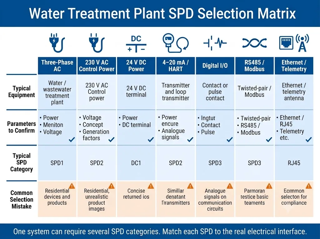
The “confirm before ordering” column is more important than the equipment name.
| Interfaz | Typical water-treatment use | Confirme antes de ordenar | Primary selection risk |
|---|---|---|---|
| CA trifásica | Main board, MCC, pump panel or VFD input | Voltage, earthing, SPD duty, Uc, Up, modes and fault level | Selecting only by Imax or pole count |
| Alimentación de 24 V CC | PLC, RTU, remote I/O, relays and instrument supply | Maximum DC voltage, current, polarity, grounding and source fault conditions | Using a low-current signal SPD as a power SPD |
| 4–20 mA or HART | Level, pressure and flow transmitters | Loop voltage, wire count, resistance budget, leakage and HART compatibility | Choosing only from the label “24 V” |
| Digital I/O or pulse | Float switch, alarm contact, valve feedback or pulse meter | Voltage, load current, polarity, switching method, frequency and shared common | Treating every digital circuit as RS485 |
| RS485 or Modbus RTU | PLC, VFD, meter, remote I/O, gateway or field instrument | Two/four wire, reference, common-mode voltage, data rate, shield and topology | Ignoring capacitance, bandwidth or conductor assignment |
| Ethernet, PoE or telemetry | Switch, RTU, radio modem, camera or SCADA link | Interface category, PoE mode, connector, data rate, shield and exposure | Assuming AC protection also protects the data port |
Similar voltage labels do not make two circuits electrically interchangeable.
How Should Level, Pressure and Flow Sensor Lines Be Protected?
Water and wastewater plants commonly use ultrasonic level transmitters, hydrostatic probes, pressure transmitters, electromagnetic flowmeters, pH instruments, conductivity analysers, turbidity sensors, pulse-output meters and float switches.
Before selecting a signal SPD, identify the actual circuit:
- Two-wire, three-wire or four-wire transmitter;
- 4–20 mA, HART, 0–10 V, pulse or dry-contact signal;
- Separate or combined power and signal conductors;
- Normal and maximum continuous operating voltage;
- Maximum circuit current;
- Permissible series resistance and voltage drop;
- Acceptable leakage current and capacitance;
- Cable shield, reference conductor and local bonding arrangement;
- Cabinet-entry, junction-box or transmitter-side installation position.
IEC 61643-21 applies to SPDs connected to telecommunications and signalling networks and defines relevant performance, safety, test and rating requirements. IEC 61643-22 addresses selection, operation, location and coordination principles for this class of SPD.[10][11]
Engineering meaning: The SPD must pass the normal measurement signal without creating an unacceptable error. Model confirmation therefore requires the transmitter datasheet, PLC or DCS input data and complete loop drawing.
For a deeper comparison, see the sensor line surge protection guide for 24 V, 4–20 mA and RS485 circuits.
Where Should 4–20 mA and HART SPDs Be Installed?
Start by evaluating the point where exposed field wiring enters the control, marshalling or remote-I/O cabinet. This helps prevent a long unprotected field cable from continuing through the cabinet to an analogue input card.
Field-side protection should also be evaluated when the transmitter is outdoors, the route is long, the cable crosses between structures or the remote equipment sits in another bonding or lightning-protection zone. This does not mean that every loop always requires two identical SPDs. The final arrangement depends on the cable route, zone concept, bonding and withstand of the connected equipment.[3][11][14]
Five loop checks that prevent selection errors
- Confirm the real loop voltage. Use the voltage present at the SPD location, including normal tolerance, rather than relying only on a “24 V” label.
- Check the loop voltage budget. The transmitter, cable, input, isolator, barrier and SPD all use part of the available voltage.
- Confirm series resistance and leakage. Excessive resistance or leakage can affect normal measurement or reduce operating margin.
- Verify HART compatibility where required. Confirm SPD frequency behaviour and the complete loop conditions against the instrument and project documentation.
- Review shield and bonding arrangements. The SPD earth connection and cable-shield strategy are related, but they are not automatically the same connection decision.
A 24 V DC power SPD and a 4–20 mA signal SPD are not automatically interchangeable
A power circuit and an analogue loop may have different current, resistance, leakage, capacitance and protection-topology requirements. Send the complete circuit drawing and both equipment datasheets before approving a model.[9][10]
How Should RS485 and Modbus Lines Be Protected?
Modbus RTU commonly uses an RS485 physical layer. The SPD must therefore match the electrical interface, wiring and data characteristics, not only the protocol name.
Confirm whether the bus is two-wire or four-wire, the conductor assignment, reference conductor, common-mode voltage, data rate, shield arrangement, termination and topology. Verify that SPD capacitance, insertion characteristics and protection level are suitable for the network.[10][11]
Place the SPD close to the cable-entry boundary, before the exposed cable continues to the PLC communication card, gateway or remote-I/O module. For a long outdoor or inter-building route, assess each connected equipment boundary.
An SPD cannot repair an incorrect RS485 network
Wrong termination, unsuitable topology, missing bias, shield current, excessive stub length, EMI or incorrect protocol configuration can also cause communication faults. Surge protection should support a correctly designed network, not replace it.
Ver el RS485 SPD wiring and selection guide for detailed A/B, reference, shield and grounding checks.
Outdoor and Inter-Building Cables Need Their Own Risk Review
Water infrastructure is physically distributed. A central plant can connect to intake structures, wells, reservoirs, aeration basins, outdoor tanks, dosing areas, lift stations and telemetry cabinets.
A buried cable is not automatically free from surge risk. It can still carry induced voltage, transmit a transient from remote equipment or connect locations that rise to different potentials during a lightning event. Water-treatment application guidance treats extended power, measuring, control and telecommunication routes as part of one coordinated protection concept.[3][14]
Review these exposed routes
- Overhead or partly overhead power feeders;
- Long buried cables to pumps, wells and outdoor panels;
- Instrument loops along tanks, basins and exposed structures;
- RS485 or Ethernet copper between buildings;
- External radio, cellular or telemetry antenna coax;
- Remote sites with a local earth electrode and a copper communication link;
- Metallic services crossing from one bonded area to another.
Where technically practical, a suitable fibre-optic connection can remove the conductive surge path from an inter-building data link. Fibre does not eliminate the need to protect the remote equipment’s power supply or other copper interfaces.
Grounding and Equipotential Bonding Determine the Real Protection Level
An SPD limits voltage by diverting surge current. It therefore needs a short, direct and low-impedance connection to the relevant PE or equipotential bonding system. A long conductor with unnecessary bends adds inductive voltage during a fast transient and can increase the voltage appearing at the protected equipment.[3][5][14]
The power SPD, signal SPD, cabinet PE bar, cable-shield treatment and structural bonding should form one coordinated design. The exact arrangement depends on the earthing system, lightning protection system, EMC concept, hazardous-area requirements where applicable and local project rules.
Important engineering boundaries
- Do not publish one universal earth-resistance value for every water plant.
- Do not use an SPD to compensate for a missing or defective protective conductor.
- Keep protected and unprotected wiring separated after the SPD where practical.
- Do not route the SPD earth connection through unnecessary loops.
- Follow the instrument and project requirements for cable-shield termination.
- Bond cabinets, metallic structures and incoming services according to the approved installation design.
Procurement meaning: A supplier can confirm an SPD model, but the panel builder or project engineer must approve the conductor route, PE connection, shield strategy and equipotential bonding layout.
Plan Status Monitoring, Inspection and Replacement
Many water and wastewater facilities contain unattended or remote equipment. A failed SPD can remain unnoticed unless the project includes a practical inspection and alarm method.
Use visible status indication where maintenance staff can inspect the cabinet. A potential-free remote contact can be connected to a PLC, SCADA system, BMS or alarm circuit when remote monitoring is required. The contact reports an SPD status change; it does not verify every fuse, conductor, PE connection or unmonitored protection point.
Record the SPD model, protected circuit, installation date, backup protection, spare-module reference and remote-contact logic in the maintenance documents. Inspection and replacement decisions should follow the project maintenance plan and model-specific instructions.[11]
For monitoring-terminal selection, see the LEEYEE remote signal SPD guide.
How to Build a Complete Water Treatment Plant SPD BOM
A useful bill of materials lists protection points and interfaces, not just product quantities. The project team should first confirm what enters each cabinet, what equipment is connected and which electrical parameters must remain unaffected.
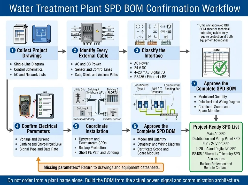
Seven-step project workflow
- Collect the drawings. Use the single-line diagram, control schematics, I/O schedule, network drawing and cable list.
- Mark every external conductor. Include AC power, DC power, analogue, digital, serial, Ethernet, antenna, shield and PE paths.
- Classify each interface. Separate AC, DC power, analogue signals, digital signals, serial communication, Ethernet and RF circuits.
- Record operating parameters. Confirm voltage, current, wires, data rate, earthing, fault conditions, cable route and connected equipment.
- Define the protection boundary. Decide where the exposed cable enters a protected zone and whether a remote equipment end also needs evaluation.
- Coordinate installation details. Check upstream and downstream SPDs, backup protection, PE route, shielding, panel space, temperature and remote indication.
- Approve documents and spare items. Match each model to its datasheet, wiring diagram, certificate scope where required, replaceable module and maintenance record.
The “information required” column must be completed before an SPD category becomes an approved model.
| Punto de protección | Interfaz | Information required | SPD category to evaluate |
|---|---|---|---|
| Utility or generator incomer | CA trifásica | Voltage, earthing, LPS, supply route, fault level and local rules | Type 1, Type 1+2 or Type 2 AC SPD |
| Process distribution board | Alimentador de CA | Upstream SPD, cable route, voltage, Uc, Up, modes and backup protection | Coordinated downstream AC SPD |
| Pump or VFD panel | AC input and auxiliary power | Drive input voltage, feeder exposure, earthing, upstream SPD and fault level | Panel-incomer AC SPD |
| PLC, RTU or remote I/O supply | AC or 24 V DC | Maximum voltage, current, polarity, source type and fault conditions | Matched AC or DC power SPD |
| Analogue input | 4–20 mA, HART or 0–10 V | Loop drawing, voltage, current, resistance, leakage and signal requirements | Analogue signal SPD |
| Digital input or output | DI, DO, pulse or contact | Voltage, current, polarity, switching type, frequency and common conductor | Digital signal or control-line SPD |
| Serial network | RS485 or Modbus RTU | Wire count, reference, voltage, shield, data rate, topology and route | RS485-compatible signal SPD |
| Plant network or telemetry | Ethernet, PoE, coax or telephone copper | Interface category, PoE mode, connector, bandwidth, shield and exposure | Interface-specific data or RF SPD |
A complete plant list normally contains several SPD categories because the facility contains several electrically different interfaces.
What LEEYEE Can Provide for Project Verification
Product evidence should be reviewed at model level. A general catalogue, factory page or certificate must not be treated as approval for every voltage, circuit or market.
Power and signal SPD scope
LEEYEE publishes separate AC, DC and signal surge protective device collections. The final product family should be chosen only after the circuit type and project standard are confirmed.[15]
RS485 and control-signal option
The published LY10 documentation identifies a DIN-rail option for communication, telemetry and remote-control signal applications. Voltage, current, transmission and terminal parameters still require model-level verification.[16]
Remote status indication
Selected power SPD configurations may include NO, NC and COM dry-contact terminals for PLC or SCADA status monitoring. Remote indication is different from signal-line surge protection.[17]
Testing and approval documents
For a project order, request the model datasheet, terminal diagram, test or certificate scope where applicable, backup-protection instruction, label drawing and sample approval record. Do not approve from a website image alone.
- Match the exact model number to the supplied datasheet.
- Check that the certificate or report covers the proposed voltage and configuration.
- Confirm terminal assignment before cabinet production.
- Approve signal performance with the connected instrument or communication interface.
- Use a sample or engineering review when project compatibility remains uncertain.
CNSPD is LEEYEE’s surge-protection-focused platform for global technical buyers. LEEYEE remains the product and supplier brand.
Errores comunes en diseño y compra
- Installing one AC SPD at the main board and assuming all PLC signal ports are protected.
- Using the same device for AC power, 24 V DC power and 4–20 mA signals.
- Choosing an AC SPD only by Imax while ignoring Uc, Up, protection modes and short-circuit conditions.
- Protecting the control-room end without assessing an exposed remote instrument or RTU.
- Installing a signal SPD far from the cable entry and leaving a long unprotected route inside the cabinet.
- Selecting an output-side VFD device without checking the drive and motor documentation.
- Calling every serial line “RS485” without confirming conductors, reference, shield and data rate.
- Ignoring Ethernet, telemetry or antenna cables because the power supply already has an SPD.
- Using long, looped or poorly bonded SPD connections.
- Ordering products before project drawings, cable routes and connected-equipment data have been reviewed.
Information to Send Before Requesting an SPD List
Sistema de energía
- Single-line diagram
- Nominal and maximum voltage
- Frequency and phase configuration
- TN, TT, IT or other earthing system
- Corriente de cortocircuito disponible
- Sistema de protección externa contra rayos
- Existing upstream SPDs
Control equipment
- Pump and VFD ratings
- PLC, RTU and remote-I/O supply voltage
- Control schematics
- Panel installation position
- DIN-rail space and environment
- Remote-status contact requirement
Field instruments
- Sensor and transmitter datasheets
- Two-, three- or four-wire arrangement
- 4–20 mA, HART, 0–10 V, pulse or digital interface
- Loop voltage and current
- Resistance, leakage or bandwidth limits
- Cable length and outdoor exposure
Communication and ordering
- RS485 or Modbus wiring
- Data rate and network topology
- Ethernet, PoE, coax or antenna details
- Inter-building cable routes
- Required standards and certificate scope
- Quantity, OEM label and documentation needs
Request a Project-Level SPD Configuration Review
LEEYEE can review the protection points shown in a water-treatment, wastewater-treatment or pumping-station design and help convert the system architecture into a model-confirmation list.
Send the single-line diagram, control voltage, loop information, communication interfaces, cable routes and required standards. The final configuration must be approved against the actual installation and connected-equipment documentation.
Water Treatment Plant Surge Protection FAQ
Is one SPD at the main switchboard enough?
Usually not when downstream equipment is connected to exposed power, sensor or communication cables. The main-board SPD protects the AC supply boundary. Pump panels, 24 V DC circuits, analogue loops, RS485, Ethernet and remote stations must be evaluated separately.
Does every water treatment plant require a Type 1 SPD?
No. Type 1 duty depends on the lightning protection concept, supply arrangement, possible lightning-current entry, risk assessment and applicable national or project rules. Some installations use Type 2 at the origin when Type 1 duty is not required or is already provided upstream.
Is electrical surge protection the same as water-hammer protection?
No. Electrical SPDs protect electrical and electronic circuits against transient overvoltage. Water hammer is a hydraulic pressure event and requires hydraulic analysis, valve-control measures, surge vessels or other water-system engineering solutions.
Where should an SPD be installed for an outdoor 4–20 mA transmitter?
Start by evaluating protection at the control-cabinet or marshalling-cabinet cable entry. Also evaluate the transmitter end when the instrument is exposed, remote or connected by a long or inter-building cable. Confirm the complete loop voltage and resistance budget before selecting a model.
Can the same SPD protect 24 V DC power and a 4–20 mA signal?
Do not assume so. The circuits may have different current, resistance, leakage, capacitance and protection-mode requirements. A combined device is suitable only when its documented electrical characteristics match the complete circuit.
Should an RS485 line be protected at both ends?
Both equipment boundaries should be evaluated for a long, outdoor or inter-building route. The final arrangement depends on cable routing, bonding, shielding, interface withstand and the protection-zone concept.
Does Modbus require a special Modbus surge protector?
Select the SPD for the physical electrical interface. Modbus RTU commonly uses RS485, so the device must match the RS485 voltage, conductor arrangement, reference, shield, data rate and topology. Modbus TCP uses Ethernet and requires an Ethernet-compatible solution.
Does a buried sensor cable still need a surge-risk assessment?
Yes. Burial can reduce some exposure, but it does not prevent induced voltage, transients arriving from remote equipment or potential differences between connected areas. Review the route, length, bonding and equipment at both ends.
Can IEC Type 1 or Type 2 be treated as the same as UL SPD Type 1 or Type 2?
No. IEC and UL classifications are based on different standards and approval systems. Confirm the target-market standard, exact product certification, electrical ratings and permitted installation position.
Where is an SPD normally evaluated in a VFD pump panel?
The incoming power side is normally the first point to assess. External control, sensor and communication lines require their own interface-specific review. Any output-side device must be approved against the drive and motor documentation.
Can a remote signal contact replace regular SPD inspection?
No. It can report the status of a monitored SPD, but it does not confirm every fuse, conductor, PE connection, cable shield or unmonitored protection point. Use remote indication as one part of a documented maintenance plan.
What information is needed to prepare a complete SPD BOM?
Provide the single-line diagram, earthing system, voltages, short-circuit current, upstream protection, control drawings, instrument loops, communication interfaces, cable routes, environmental conditions, required standards, quantities and OEM documentation needs.
Guías técnicas relacionadas
Referencias
- Comisión Electrotécnica Internacional. IEC 62305-2:2024, Protection against lightning — Part 2: Risk management.
- Comisión Electrotécnica Internacional. IEC 62305-3:2024, Protection against lightning — Part 3: Physical damage to structures and life hazard.
- Comisión Electrotécnica Internacional. IEC 62305-4:2024, Protection against lightning — Part 4: Electrical and electronic systems within structures.
- Comisión Electrotécnica Internacional. IEC 60364-4-44:2024, Low-voltage electrical installations — Protection against voltage disturbances and electromagnetic disturbances.
- Comisión Electrotécnica Internacional. IEC 60364-5-53:2019+A1:2020+A2:2024, Selection and erection of electrical equipment — Devices for protection, isolation, switching, control and monitoring.
- Comisión Electrotécnica Internacional. IEC 61643-01:2024, Low-voltage surge protective devices — Part 01: General requirements and test methods.
- Comisión Electrotécnica Internacional. IEC 61643-11:2025, Surge protective devices connected to AC low-voltage power systems — Requirements and test methods.
- Comisión Electrotécnica Internacional. IEC 61643-12:2020, Surge protective devices connected to low-voltage power systems — Selection and application principles.
- Comisión Electrotécnica Internacional. IEC 61643-41:2025, Surge protective devices connected to DC low-voltage power systems — Requirements and test methods.
- Comisión Electrotécnica Internacional. IEC 61643-21:2025, Surge protective devices connected to telecommunications and signalling networks — Requirements and test methods.
- Comisión Electrotécnica Internacional. IEC 61643-22:2015, Surge protective devices connected to telecommunications and signalling networks — Selection and application principles.
- UL Solutions. Surge Protection Device Testing and Certification Services.
- UL Solutions Product iQ. Example UL 1449 SPD certification record showing SPD Type, VPR, MCOV, In and SCCR fields.
- DEHN SE. Retrofitting Sewage Plants with Lightning and Surge Protection Measures, application white paper WPX032/EN/0122.
- LEEYEE. Surge Protection Product Collections: AC, DC and Signal SPDs.
- LEEYEE. LY10 RS485 DIN-Rail Data Signal Surge Protective Device.
- LEEYEE. Dispositivo de Protección contra Sobretensiones con Contacto de Señal Remota.
Standards, national adoptions, certification records and project specifications can be revised. Confirm the applicable edition, local requirements, exact model scope and manufacturer installation instructions before final design, procurement or approval.
LEEYEE is a specialized surge protection and low-voltage protection supplier. CNSPD is LEEYEE’s surge-protection-focused platform for global technical buyers.
