
This automatic transfer switch selection guide is written for panel builders, generator integrators, electrical contractors, distributors and OEM buyers who already understand the basic purpose of an ATS and now need to specify the correct device for a real project. The selection should start with the power architecture and transferred load, then move through current, voltage, poles, neutral arrangement, transition method, short-circuit coordination and controller functions. If you first need the basic operating principle, see ¿Qué es un Interruptor de Transferencia Automática?
Índice
How do you select an automatic transfer switch?
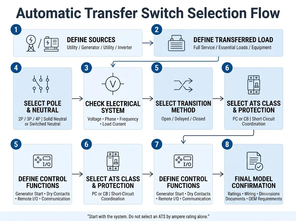
Start with the electrical system, not with the ampere number on the front of the ATS.
Confirm the two power sources and the load that will actually pass through the transfer point. Then calculate the preliminary design current, confirm system voltage and phase, decide whether the neutral must be switched, choose the required transition method, define the short-circuit protection architecture, and specify generator control, dry contacts or communications where required.
For IEC projects, transfer switching equipment is covered by IEC 60947-6-1. The current edition is IEC 60947-6-1:2026, published on 2 April 2026. It covers transfer switching equipment within its stated voltage scope and includes dedicated requirements for closed-transition ATSE and stand-alone ATS controllers. [1]
| Pregunta de selección | Qué Confirmar | Common Wrong Shortcut |
|---|---|---|
| What will the ATS carry? | Full service, essential-load feeder, generator output or dedicated equipment | “Match the generator kW” |
| What current is required? | Actual transferred-load design current and switching duty | “Use the main breaker number automatically” |
| 2P, 3P or 4P? | Phase conductors plus neutral and grounding strategy | “Three phase always means 4P” |
| Open or closed transition? | Load interruption tolerance and source relationship | “Closed transition means zero outage in every event” |
| PC or CB class? | Who provides short-circuit interruption and protection | “CB class is always better” |
| Need generator or BMS control? | Start/stop, delays, dry contacts, alarms and communication | “Automatic means every control function is included” |
Significado para el comprador: the most useful input is a one-line diagram. If that is unavailable, send both source details, load current and type, phase, neutral/grounding arrangement, required transition method, upstream protection and controller I/O requirements.
1. Use this ATS selection sequence before comparing models
The fastest way to avoid a wrong ATS purchase is to keep the engineering decisions in the correct order. Rated current matters, but it is only one part of the selection.
Significado para el comprador: two transfer switches marked “63 A, 4P” can still differ in utilisation category, short-circuit capability, transition method, control functions, terminal capacity and certification scope.
2. What size automatic transfer switch do you need?
The current rating should be selected from the actual transferred-load design current and duty. Generator power is useful source information, but generator kW or kVA alone does not define the correct ATS rating.
The most important step is identifying where the ATS sits in the one-line diagram before calculating its current.
| ATS Location | Main Sizing Basis | Secondary Check |
|---|---|---|
| Full-service transfer | Maximum design current through the transferred service path | Generator capacity, load management, protection and fault current |
| Essential-load board | Calculated current of the transferred essential loads | Feeder protection and load-shedding strategy |
| Dedicated equipment | Equipment design current and switching duty | Starting current and acceptable interruption |
| Utility-to-utility transfer | Load current that either source must supply | Neutral design, source relationship and transition requirement |
Conclusión de compras: establish the transferred current path before selecting an ATS frame size.
Preliminary ATS current calculations
If project data is supplied in apparent power, the following equations can estimate current during early selection. For three-phase calculations, use line-to-line voltage and assume a balanced load. These calculations are preliminary; final ATS approval still requires the actual load characteristics, utilisation category, installation conditions and manufacturer data.
30 kVA, 400 V three-phase distribution load
The calculated current is approximately 43.3 A. A 50 A current option may therefore be a starting point from current alone. The next checks are neutral switching, utilisation category, installation conditions and short-circuit coordination.
3. Utility-generator, utility-utility or generator-generator?
The source arrangement changes the operating sequence. A technically useful ATS enquiry should therefore identify both sources instead of saying only “dual power”.
Utility → Generator
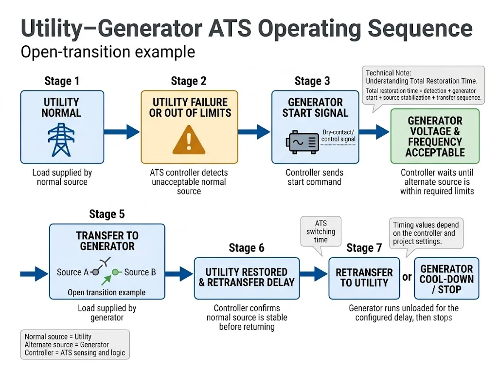
Confirm source-failure sensing, generator start command, generator source acceptance, transfer delay, retransfer delay and generator stop sequence. Cummins documents these as separate stages in a typical automatic utility-generator transfer sequence. [5]
Utility → Utility
An engine-start sequence is normally unnecessary. Define preferred source, source acceptance conditions, transfer/retransfer delays and the permitted transition method.
Generator → Generator
Confirm how each generator is started and stopped, which source has priority, whether alternation is required and how the system responds if a source fails to become acceptable.
Utility → Inverter / ESS
Confirm inverter output voltage and frequency, neutral bonding, source behaviour and the inverter manufacturer's transfer requirements before fixing the ATS configuration.
4. How do you choose 2P, 3P or 4P ATS?
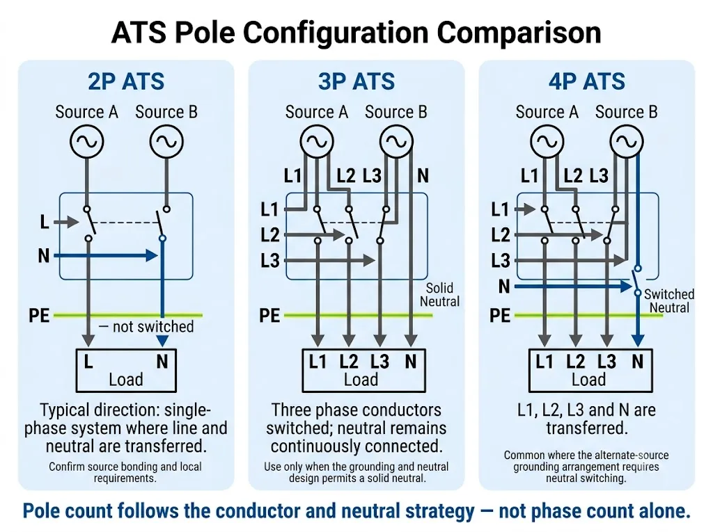
Choose the pole configuration from the conductors that must be transferred and from the system neutral/grounding design. Phase count by itself is not enough.
Focus on what happens to the neutral conductor. That decision usually explains the difference between 3P and 4P transfer arrangements.
| Configuración | Common Direction | Project Check |
|---|---|---|
| 2P | Common in single-phase arrangements where two conductors are transferred | Confirm which conductor is neutral, bonding and local requirements |
| 3P | Three phase conductors switched while neutral remains solid, or a three-wire system | Confirm that a continuous neutral is correct for the grounding design |
| 4P | L1, L2, L3 and neutral are transferred | Confirm that switched-neutral operation is required by the source and grounding arrangement |
Schneider Electric's ASCO guidance distinguishes transfer switches with solid and switched neutrals. It states that selecting a solid or switched neutral depends on the electrical distribution system and the grounding relationship of the alternate source, including separately derived source arrangements. [4]
5. Open transition vs delayed transition vs closed transition
Open transition is a break-before-make transfer. The connected source is disconnected before the alternate source is connected, so a short interruption occurs.
Delayed transition is an open transition with an intentional OFF interval. This can be useful when residual voltage, motors, transformers or process behaviour require a pause before the alternate source is connected.
Closed transition allows a brief overlap between two acceptable and synchronized sources during an eligible transfer. IEC 60947-6-1:2026 includes specific requirements for ATSE with closed-transition capability in Annex D. [1]
| Transition | Source Sequence | Selection Trigger |
|---|---|---|
| Open | Source 1 opens → Source 2 closes | A brief interruption is acceptable |
| Delayed | Source 1 opens → OFF delay → Source 2 closes | The load or residual voltage requires a deliberate pause |
| Closed | Synchronized sources overlap briefly | Planned transfer should minimize interruption and temporary paralleling is permitted |
Significado técnico: a critical no-break load may still require a UPS or another continuity architecture. Do not specify closed transition merely because a project uses the phrase “no downtime”.
6. PC class vs CB class ATS: decide who clears a short circuit
IEC 60947-6-1 classifies transfer switching equipment according to short-circuit capability. ABB summarizes the practical distinction between Class PC and Class CB as follows. [2]
| Clase | Short-Circuit Role | Panel Design Meaning |
|---|---|---|
| Clase PC | Capable of making and withstanding short-circuit currents but not intended to break them | Short-circuit interruption must be provided by appropriately coordinated protective devices |
| Clase CB | Capable of making, withstanding and intended to break short-circuit currents, with overcurrent releases | Breaker-based transfer architecture; system protection and selectivity still require engineering review |
Significado para el comprador: Class PC is not an inferior version of Class CB. They are different transfer and protection architectures. Select the architecture required by the project rather than treating the class name as a quality grade.
7. Short-circuit capability: the ATS current rating is not enough
A normal-current rating such as 63 A tells the buyer about the ATS operating-current range under stated conditions. It does not by itself prove that the transfer equipment is suitable for the prospective fault current at the installation point.
For IEC projects, verify the exact transfer switch short-circuit data and the manufacturer-specified protective-device conditions. Depending on the ATS design, relevant parameters can include withstand capability, making capability or a conditional short-circuit rating. The required check must use the exact model documentation rather than a generic ATS value. [1][2]
For North American projects, UL Solutions identifies UL 1008 as the applicable transfer-switch standard within its certification scope. The product marking and tested conditions must be checked for the exact device and application. [7]
8. Integrated controller or separate ATS controller?
Some automatic transfer switches combine the switching mechanism and controller in one device. Other systems use separate switching devices with a stand-alone ATS controller. IEC 60947-6-1:2026 explicitly includes stand-alone ATS controllers in Annex E. [1]
Integrated ATS Controller
- Compact panel architecture
- Less external control wiring
- Useful when the built-in sequence matches the project
Separate ATS Controller
- More flexible sensing and timing options
- Potentially more I/O and communication functions
- Useful for larger or more complex transfer assemblies
For OEM panel design, ask which sensing, timing, I/O and communication functions are required. A display screen alone does not define the controller capability.
9. Generator start signals, dry contacts and remote monitoring
Automatic transfer operation does not mean that every ATS includes the same external control interfaces. Generator control, dry contacts and communications should therefore be specified individually.
Generator start and stop sequence
In a typical utility-generator arrangement, the ATS control monitors the normal source. When the source remains unacceptable for the programmed delay, it signals the generator to start. The controller then waits for the generator source to reach acceptable conditions before transferring the load. When normal power returns and remains acceptable, the controller can begin the retransfer sequence and subsequently initiate the generator stop sequence. [5]
Dry contacts
A dry contact is a voltage-free relay contact used to exchange a status or command signal with another controller. Project requirements may include source availability, transfer position, alarm, remote test, inhibit or generator start. The exact NO/NC logic and contact rating must be confirmed from the selected controller documentation.
Supervisión remota
For BMS, PLC, telecom or unmanned installations, replace the vague requirement “remote monitoring” with a defined I/O or protocol list. Typical project questions include:
- Is Source A available?
- Is Source B available?
- Which source is connected to the load?
- Is there a common alarm output?
- Is remote test, transfer or inhibit required?
- Is a generator start/stop output required?
- Is RS485, Modbus, Ethernet or another protocol required?
10. Match the ATS to the load type and utilisation category
The same current number can represent different switching duties. General distribution loads, motors, transformers, UPS inputs and mixed loads can impose different starting, inrush and transfer requirements.
Do not stop at the running current. For motor- or transformer-heavy panels, load duty becomes a major selection factor.
| Tipo de carga | What Changes the Selection | What to Send the Supplier |
|---|---|---|
| General distribution / resistive | Design current, voltage and required utilisation category | Load schedule or feeder design current |
| Motors / pumps / compressors | Starting current, switching duty, residual voltage and restart sequence | Motor kW, starting method and operating duty |
| Transformers | Magnetizing inrush and transfer timing | Transformer kVA and available inrush information |
| UPS / VFD / sensitive electronics | Ride-through capability, source quality and interruption tolerance | Equipment input specification and acceptable transfer break |
Significado técnico: if the project is motor-heavy, do not assume that a compact AC-31B ATS is suitable simply because its ampere rating exceeds the motor running current.
11. Where does LEEYEE ATS-63 fit?
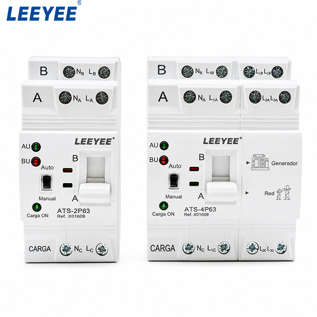
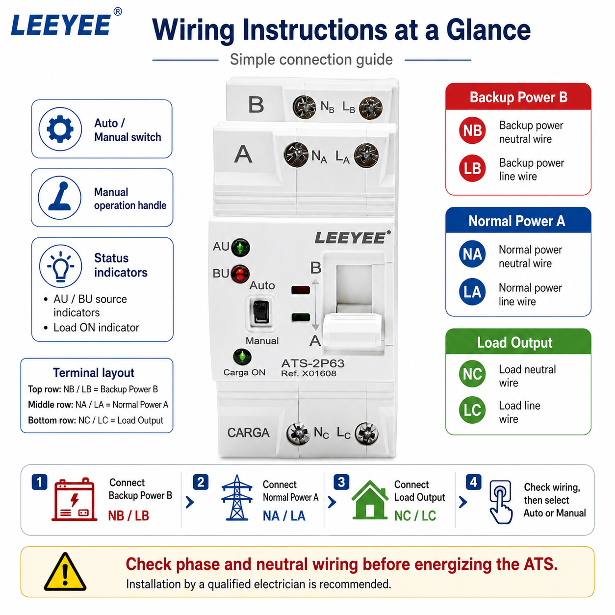
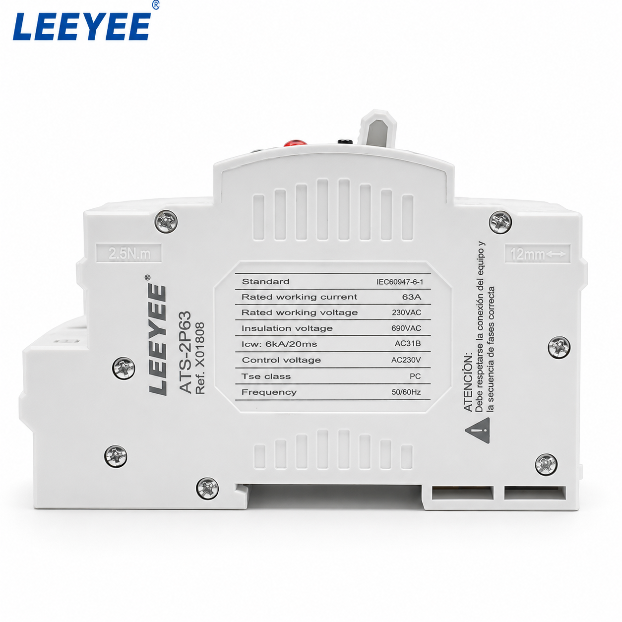
LEEYEE ATS-63 is a compact DIN-rail automatic transfer switch for smaller AC backup systems. The current LEEYEE product page lists 6 A, 10 A, 16 A, 20 A, 25 A, 32 A, 40 A, 50 A and 63 A ratings; 2P and 4P configurations; AC110 V, AC220 V and AC400 V versions; 50/60 Hz; Class PC; AC-31B utilisation category; transfer switching time below 50 ms; and rated short-circuit current Iq of 5 kA. [6]
| ATS-63 Can Be a Starting Point When… | Use Another ATS Architecture When… |
|---|---|
| The required operating current is within the listed 6–63 A range and the exact model rating matches. | The transferred load exceeds 63 A. |
| 2P or 4P matches the approved conductor and neutral arrangement. | The project specifically requires a 3P or another transfer configuration. |
| The load duty is compatible with the listed AC-31B utilisation category. | The load requires another utilisation category or model-specific switching performance. |
| The project can accept the transfer behaviour of the selected ATS-63 model. | Closed transition, bypass/isolation or source synchronization is required. |
| The project short-circuit conditions and protection match the documented device limits. | The available fault current or required coordination is outside the documented application. |
| Basic compact two-source automatic transfer is required. | Advanced communication, event logging or complex generator sequencing is mandatory. |
For the current model parameters, installation limits, dimensions and wiring information, use the Página del producto LEEYEE ATS-63. A selection guide should direct a buyer to the correct architecture; it should not force every project into one compact ATS model.
12. Common ATS selection mistakes that cause panel rework
| Error | Por qué crea riesgos | Better Check |
|---|---|---|
| Choosing by generator kW only | Generator power does not directly define the transferred-load current or ATS duty | Calculate the current at the actual transfer point |
| Choosing 4P only because the system is three-phase | Neutral switching depends on the grounding and source arrangement | Confirm the neutral strategy first |
| Ignoring utilisation category | Motor and transformer switching duties can differ from general distribution duty | Match the load and required utilisation category |
| Ignoring available fault current | An ATS can carry normal current but still be unsuitable for the project fault condition | Verify short-circuit data and protective-device coordination |
| Assuming “automatic” includes every generator or BMS function | Controller I/O and communication vary by model | Provide a defined sequence and I/O list |
| Approving from a product photo and ampere label | Wiring, terminals, dimensions, controller logic and documents can differ | Approve the exact item code and technical documentation |
13. Before ordering: ATS RFQ checklist for panel builders and OEM buyers
Send these parameters before requesting a model recommendation
- Normal source type
- Alternate source type
- Preferred source
- Source A voltage
- Source B voltage
- System frequency
- Monofásico o trifásico
- Transferred-load design current
- Load type and inrush information
- 2P / 3P / 4P requirement
- Neutral and grounding arrangement
- Open / delayed / closed transition
- PC or CB requirement if specified
- Corriente de falla prospectiva
- Disyuntor o fusible de cabecera
- Generator start/stop requirement
- Transfer and retransfer delays
- Required dry-contact I/O
- Required communication protocol
- Manual/test/bypass requirement
- Panel mounting space
- Ambient temperature and altitude
- Target market and standard
- Required certificates or documents
- Cantidad
- Requisito de etiqueta OEM o embalaje
“Need ATS for [utility-generator / utility-utility / generator-generator / other]. Source A: [V / Hz / phase]. Source B: [V / Hz / phase]. Transferred load: [A + load type]. Pole requirement: [2P / 3P / 4P]. Neutral: [solid / switched / unknown]. Transition: [open / delayed / closed]. Upstream protection: [device and rating]. Available fault current: [kA if known]. Generator start: [yes / no]. Dry contacts: [list]. Communication: [protocol]. Quantity: [ ]. Destination: [ ]. Required standard/documents: [ ].”
Need the ATS configuration checked before panel approval?
Send the one-line diagram or the checklist above. LEEYEE can review whether the requested current, voltage, pole arrangement and ATS-63 operating range match the stated project conditions before quotation or sample approval.
If the project falls outside the documented ATS-63 range, the transfer architecture should be reconsidered rather than forcing the compact model into the design.
Preguntas frecuentes
¿Qué tamaño de interruptor de transferencia automática necesito?
Start with the design current that will actually pass through the transfer point. Then select an available ATS rating that can carry that duty and verify voltage, phase, utilisation category, neutral arrangement, transition method, installation conditions and short-circuit coordination.
Should the ATS match the generator rating or the main breaker?
Neither rule is universally correct. A full-service ATS may need to carry the normal service path even where the generator is smaller and load management is used. An essential-load ATS can instead be selected around the transferred essential-load feeder. The one-line diagram determines which current path matters.
Do I need a 3P or 4P ATS for a three-phase system?
Use a three-pole arrangement when the three phase conductors are transferred and a solid neutral is correct for the system. Use a four-pole arrangement when the neutral also needs to be transferred. The final decision depends on the grounding and source arrangement and applicable project requirements. [4]
Is a 4P ATS always safer than a 3P ATS?
No. More poles do not automatically mean a safer design. Switching the neutral must be intentional and compatible with the system grounding arrangement.
What is the difference between Class PC and Class CB ATS?
Class PC transfer equipment can make and withstand short-circuit current but is not intended to interrupt it. Class CB equipment is capable of making, withstanding and interrupting short-circuit current and includes overcurrent releases. [2]
Does an automatic transfer switch provide overload or short-circuit protection?
Do not assume that it does. A Class PC ATS depends on appropriately coordinated protective devices for short-circuit interruption. A Class CB architecture includes overcurrent releases, but the complete system still requires protection and selectivity review. [2]
Does an ATS need a generator start contact?
A utility-generator system normally requires a defined interface to start the generator unless another controller performs that function. The contact type, logic, timing and generator-controller compatibility must be confirmed for the actual system. [5]
Does every ATS have dry contacts or Modbus?
No. Status contacts, remote commands and communications are controller-specific features. Put the required I/O and protocol into the project specification or RFQ.
Can closed transition eliminate every power interruption?
No. Closed transition can minimize interruption during an eligible transfer between two live, synchronized sources. If the normal source has already failed, it is not available for overlap with the alternate source. [3]
What standard applies to ATS in IEC projects?
IEC 60947-6-1 is the core international standard for transfer switching equipment within its scope. The current fourth edition, IEC 60947-6-1:2026, applies to transfer switching equipment up to 1,000 V AC or 1,500 V DC and includes dedicated annexes for closed-transition ATSE and stand-alone ATS controllers. [1]
Is LEEYEE ATS-63 suitable for motor loads?
The current ATS-63 product data lists utilisation category AC-31B. Do not automatically specify it for a motor-heavy application that requires another utilisation category. Provide the motor and switching-duty information for project confirmation or select equipment with the required duty rating. [6]
Referencias
- [1] IEC. IEC 60947-6-1:2026 — Low-voltage switchgear and controlgear — Part 6-1: Multiple function equipment — Transfer switching equipment. Fourth edition, published 2 April 2026. Página de publicaciones oficiales de la IEC.
- [2] ABB. How to Select an Automatic Transfer Switch Class. Technical white paper explaining IEC Class PC, Class CB and Class CC transfer switching equipment and their short-circuit functions. ABB technical white paper.
- [3] Schneider Electric. What Is a Transfer Switch? Technical explanation of ATS operation and closed-transition behaviour during transfer and retransfer. Schneider Electric technical article.
- [4] Schneider Electric / ASCO. Neutral Configurations in Transfer Switches. Data bulletin covering solid-neutral and switched-neutral configurations and their relationship to alternate-source grounding. Schneider Electric / ASCO data bulletin.
- [5] Cummins. Application Manual — Transfer Switches. Technical application guidance describing normal-source monitoring, generator start, transfer delay, retransfer and generator stop sequence. Cummins transfer-switch application manual.
- [6] LEEYEE. ATS-63 Automatic Transfer Switch for Solar & Home Backup. Current product data for rated current, 2P/4P configurations, voltage, frequency, Class PC, AC-31B, Iq, transfer time, environmental limits, dimensions and wiring information. Página del producto LEEYEE ATS-63.
- [7] UL Solutions. Switch Certification and Evaluation Services. Transfer-switch certification and evaluation information, including UL 1008. Soluciones UL.
Engineering note: final ATS selection must follow the project one-line diagram, applicable local electrical requirements, the exact transfer-switch and controller documentation, and the approved short-circuit/protection coordination. Where a source, neutral, load-duty, fault-current or controller requirement is unknown, treat it as an open project-confirmation item rather than assuming a value.
