
Utilice Tipo 1+2 en la etapa de entrada
It is commonly considered for main distribution boards and buildings with an external lightning protection system when one device must provide both lightning-current and surge performance.
Combined lightning-current and surge protection for main distribution boards, distributors, panel builders and OEM projects. Send Uc, Iimp, polos y sistema de puesta a tierra para confirmar el modelo correcto y el alcance de la documentación.
A Type 1+2 SPD should not be selected by pole count alone. Confirm where it is installed, how neutral and PE are arranged, the required Iimp path, Uc and the external backup protection.
It is commonly considered for main distribution boards and buildings with an external lightning protection system when one device must provide both lightning-current and surge performance.
3P, 4P and 3P+N are not interchangeable labels. The correct arrangement depends on TT, TN-S or TN-C conductors and whether the design uses 4+0 or 3+1 protection.
For MOV+GDT arrangements, L-N and N-PE values can differ. Ask whether Iimp is stated per pole, per protection path or as a total value.
| Sistema de CA | Configuración inicial común | Concepto de protección | Confirmación clave antes del pedido |
|---|---|---|---|
| TN-S / TT monofásico | Configuración 1P+N o 2P verificada | L-N más N-PE, o configuración de todos los modos según el diseño | Uc, ruta N-PE, asignación de Iimp y protección de respaldo |
| TN-C trifásico | 3P | Conductores de fase a PEN sin un neutro separado en el punto de instalación | Disposición real de PEN, Uc y condiciones de cortocircuito |
| TN-S trifásico | 4P o 3P+N | 4+0 o 3+1 según la topología del proyecto | Tratamiento del neutro, ruta N-PE, Up y tendido de conductores |
| TT trifásico | Disposición 3P+N verificada | Normalmente rutas MOV L-N más ruta GDT N-PE | Corriente de impulso N-PE, corriente subsiguiente y cobertura documental |
The classification changes the test parameters, expected installation stage and procurement checks. The page below focuses only on the combined Type 1+2 product range.
Diseñado en torno a la prueba de corriente de rayo de 10/350μs y al rendimiento Iimp.
Un SPD evaluado tanto para el rendimiento de corriente de rayo de 10/350μs como para el de corriente de sobretensión de 8/20μs.
Diseñado en torno a la prueba de 8/20μs utilizando In e Imax como parámetros principales de corriente.
Six existing configurations cover single-path, multi-pole and MOV+GDT arrangements. Exact Uc, Up, Iimp, In and backup-fuse data are checked against the selected version.
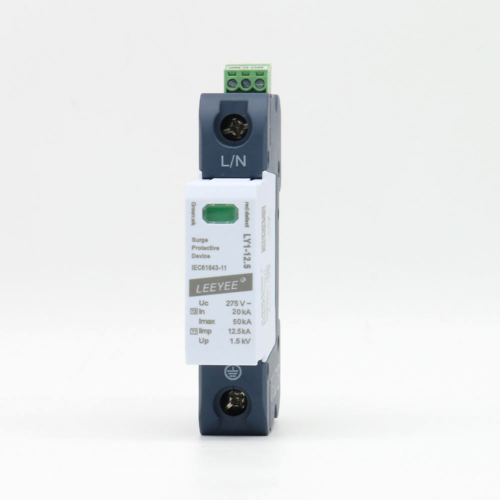
Módulo enchufable Tipo 1+2 de un solo polo para una ruta de protección verificada.
Higher-Uc versions can have different Iimp and backup-fuse limits. Confirm the exact voltage suffix.
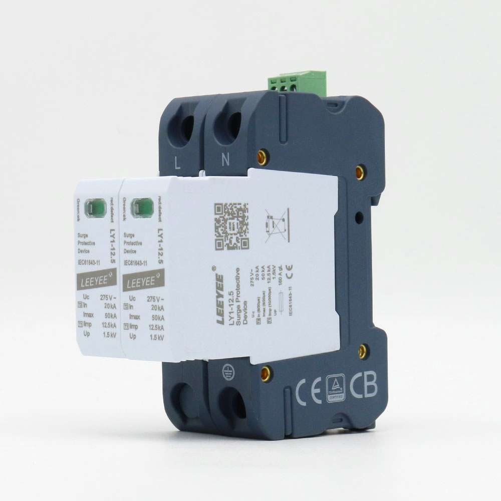
Conjunto enchufable de dos polos para un diseño de sistema que requiere dos conductores protegidos.
A 2P enclosure does not by itself prove the correct L-N/N-PE topology. Verify the internal protection mode.
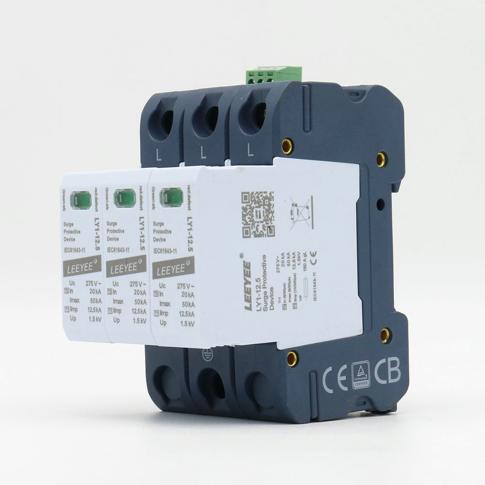
SPD enchufable de 3 polos Tipo 1+2 para configuraciones verificadas de tres conductores.
Commonly considered where no separate neutral conductor is protected at the installation point. Confirm the actual system.
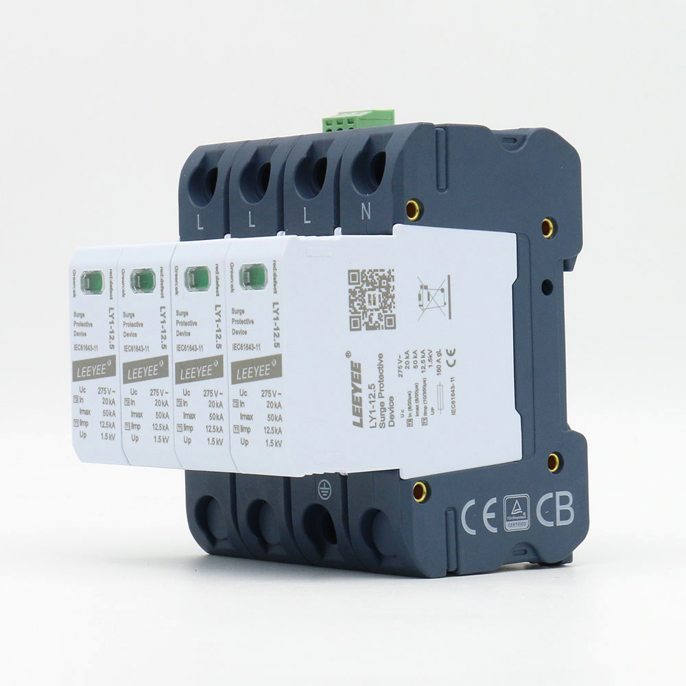
SPD enchufable de 4 polos Tipo 1+2 para una configuración de protección 4+0 verificada.
Do not treat “4P” as automatically identical to a 3+1 MOV+GDT configuration. Check the protection paths.
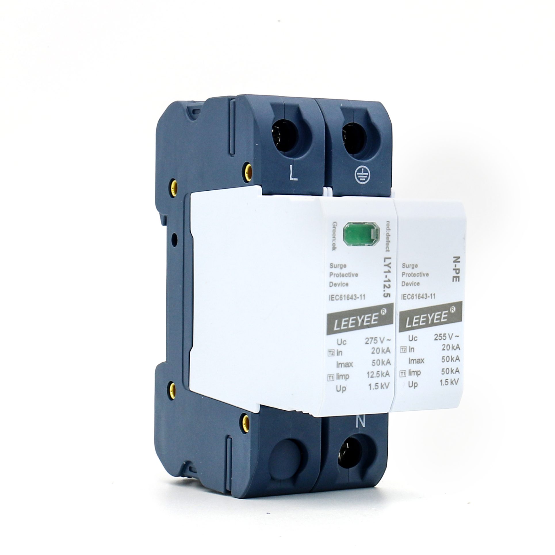
Disposición L-N MOV más N-PE GDT para una topología monofásica verificada.
Confirm N-PE follow-current behavior, Up and the external backup-fuse requirement for the exact version.
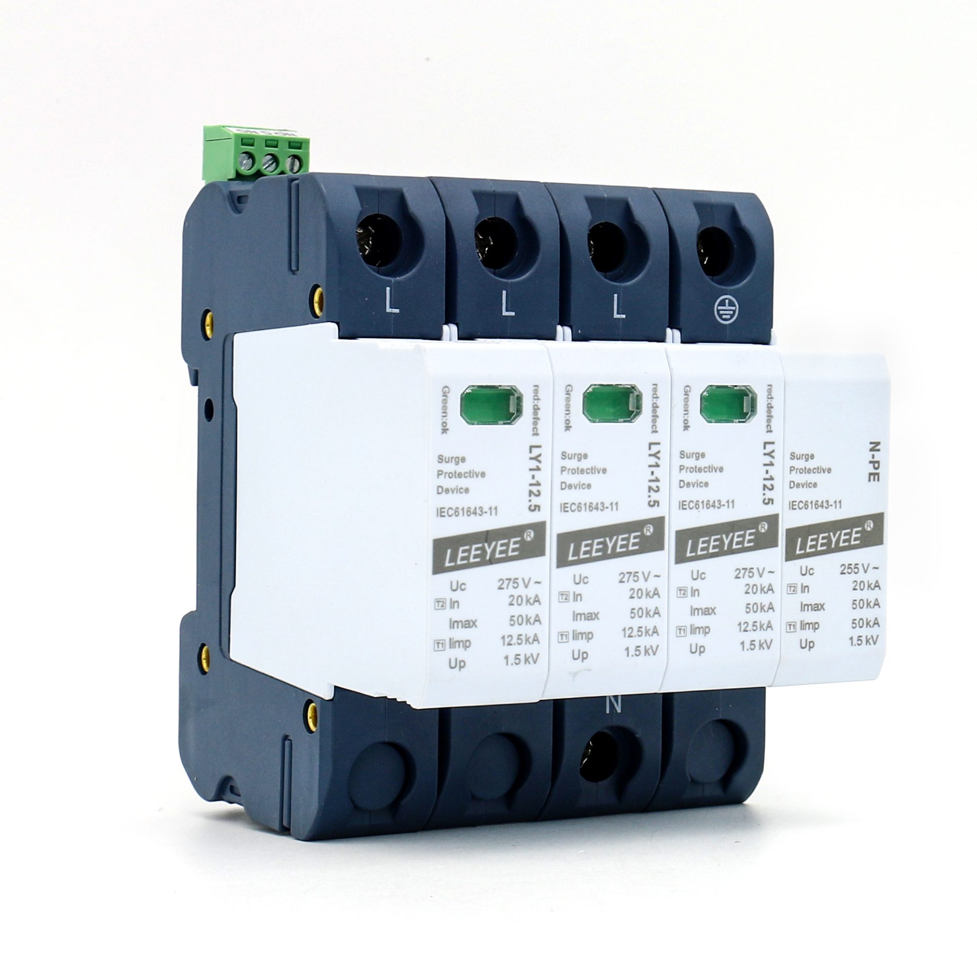
Tres rutas MOV L-N más una ruta GDT N-PE para una topología 3+1 verificada.
L-N and N-PE values are intentionally different. Review each path instead of relying on one headline current value.
A model can look correct by Type and pole count but still be unsuitable because the current path, Uc, topology or backup protection was not verified.
Pregunte cómo el declarado Se asigna una corriente de 10/350μs.. A headline number can refer to one pole, one path or a complete N-PE path depending on the model.
Choose Uc against the actual phase-to-neutral or phase-to-earth voltage, tolerances and temporary overvoltage exposure. Un Uc más alto no es automáticamente mejor.
A 4P MOV arrangement and a 3P+N MOV+GDT arrangement create different paths. Confirm gestión del neutro, comportamiento N-PE y sistema de puesta a tierra del proyecto.
The SPD’s internal thermal disconnector does not replace all external short-circuit protection. Check the fusible de respaldo máximo, la corriente de falla prospectiva y la longitud del conductor.
Equipment photos are supporting evidence, not a substitute for a model-specific test report. The exact Type, Uc, poles and branding configuration must still match the document scope.
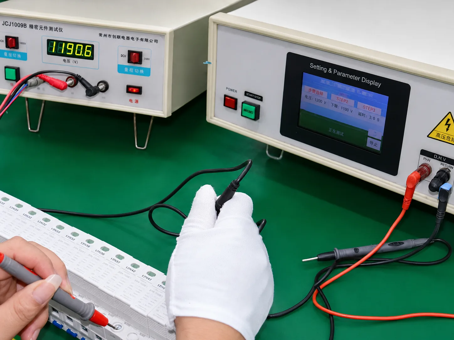
Los componentes de protección principales se verifican antes de integrarse en el ensamblaje final del SPD.
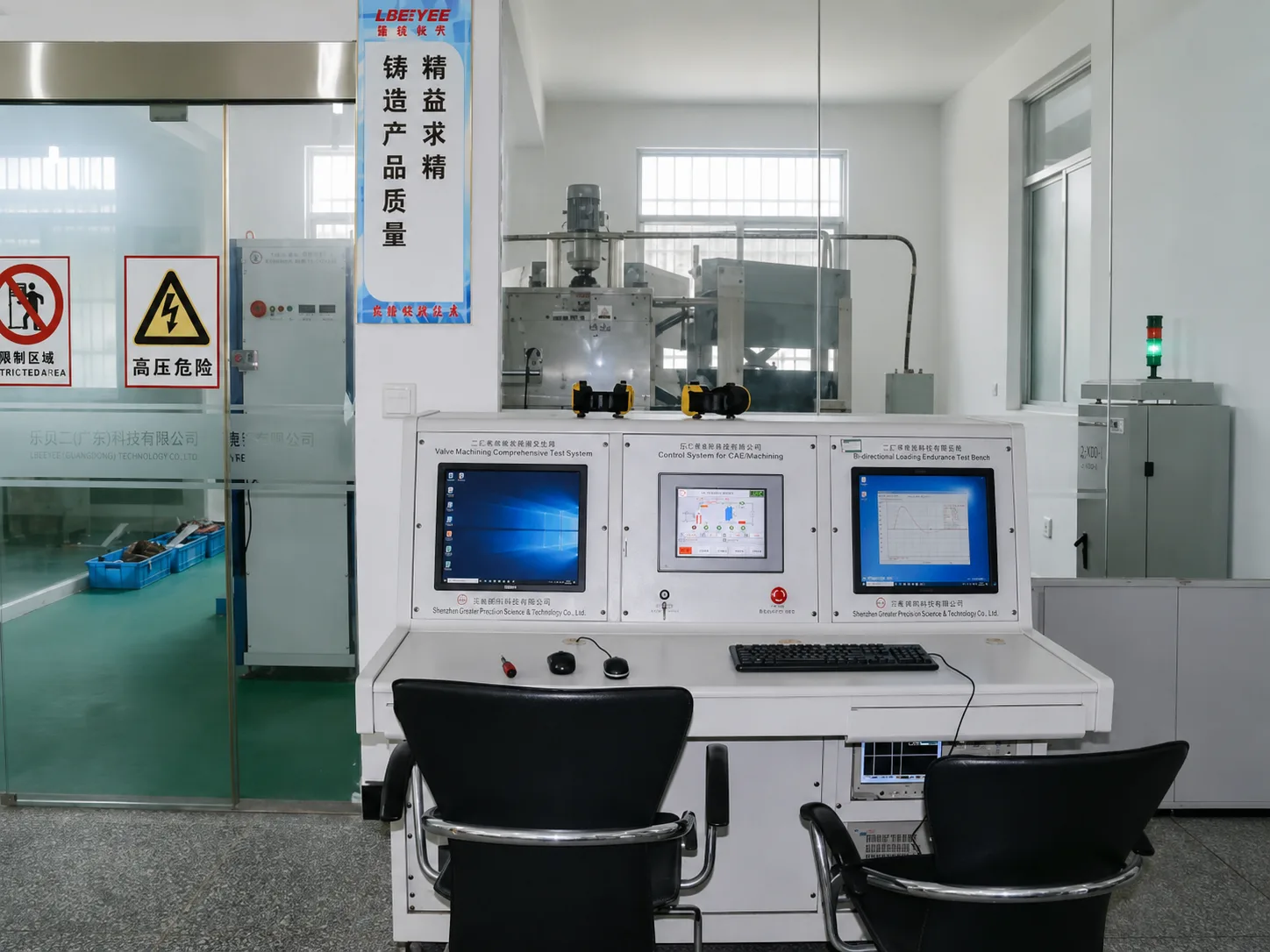
Type 1+2 procurement requires evidence for both lightning-current and surge-current performance, according to the exact model.
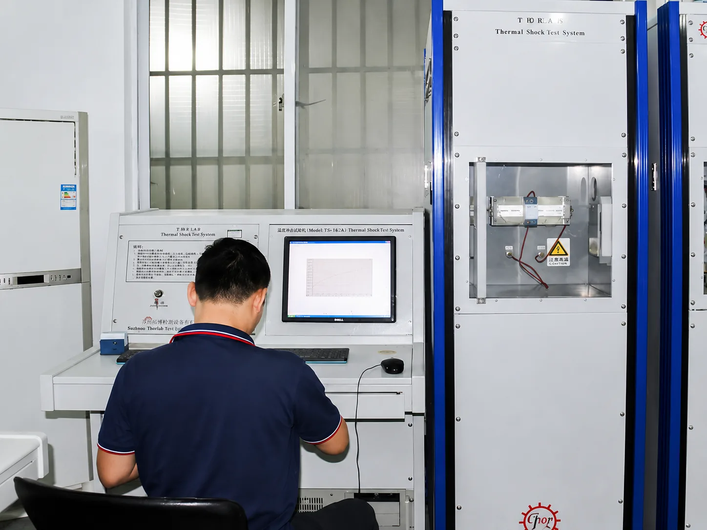
Thermal behavior matters because MOV ageing and abnormal voltage exposure can create a safety risk if disconnection is unreliable.
Límite del documento: Certification and test-document availability depends on the exact model, voltage, SPD Type, pole configuration, brand and manufacturer information. Submit the required version for confirmation.
For distributors, panel builders and private-label buyers, commercial approval is not complete until the selected model and all customer-facing documents describe the same product.
Share the intended market, system, quantity and branding requirement so LEEYEE can identify the relevant model and available documentation.
A short approval sequence reduces the risk of ordering the correct enclosure with the wrong electrical or document configuration.
These answers cover the most common procurement errors. For a model recommendation, send the actual system voltage, earthing arrangement, poles and quantity.
Aclaración de marca: LEEYEE es la marca del producto. CNSPD.com es la plataforma de protección contra sobretensiones de LEEYEE para compradores globales.
Send the essential project details now. We will use them to confirm the suitable Type 1+2 model, document scope and quotation requirements.
Your project details will be used to review the suitable model, documentation scope and quotation requirements.