
SPD spark gap N-PE adalah jalur perlindungan lonjakan yang didedikasikan yang dipasang antara netral dan tanah pelindung di banyak pengaturan 3+1 dan 1+1. Ini juga dapat dijelaskan sebagai penangkal lonjakan N-PE, penangkal arus petir N-PE atau modul perlindungan spark-gap N-PE.
Bagi pembuat panel dan pembeli OEM, pertanyaan penting bukan hanya apa komponen tersebut. Anda perlu tahu mengapa ia digunakan di sistem TT, bagaimana perbedaannya dari modul MOV biasa, dan data spesifik jalur mana yang harus diverifikasi sebelum menyetujui keseluruhan SPD.
Daftar Isi
Jawaban Cepat: Apa Itu SPD Spark Gap N-PE?
SPD celah percikan N-PE adalah elemen pengalih tegangan yang terhubung antara netral dan tanah pelindung. Selama operasi normal, ia tetap dalam status impedansi tinggi. Selama lonjakan, ia beralih ke konduksi dan menyediakan jalur pelepasan dari N ke PE.
Dalam SPD tiga fase 3+1 yang khas, tiga jalur pembatas tegangan melindungi L1-N, L2-N, dan L3-N. Jalur keempat melindungi N-PE. Penangkap berbasis celah percikan N-PE digunakan dalam konfigurasi 3+1 dan 1+1 yang terdocumentasi untuk sistem TT dan TN terpilih, tergantung pada desain instalasi dan instruksi produsen.[3][5]
| Jalur perlindungan | Fungsi khas | Pemeriksaan pembeli utama |
|---|---|---|
| L1-N, L2-N, L3-N | Batasi tegangan lonjakan fase-ke-netral | Uc, Up, In, Imax atau Iimp |
| N-PE | Menyediakan jalur pelepasan netral-ke-tanah yang umum | Uc, Up, TOV, arus lanjutan, In atau Iimp |
Makna pembeli: jangan pernah menyetujui “SPD 4P” hanya berdasarkan jumlah kutub. Konfirmasi apakah sirkuit internal adalah 3+1 atau 4+0 dan verifikasi jalur N-PE secara terpisah.
Apa Arti Perlindungan N-PE?
N berarti netral. PE berarti tanah pelindung. Perlindungan N-PE berarti bahwa SPD mencakup jalur perlindungan lonjakan yang ditentukan antara kedua konduktor ini.
Jalur N-PE tidak dimaksudkan untuk mengangkut arus beban normal. Tujuannya adalah untuk mengendalikan tegangan berlebih antara netral dan tanah selama peristiwa transien.
Dalam pengaturan 3+1, arus lonjakan dari konduktor fase pertama kali ditangani oleh tiga jalur L-N. Elemen N-PE kemudian menyediakan rute pelepasan bersama menuju tanah pelindung.
Mengapa 3+1 SPD Umum di Sistem TT?
Dalam sistem TT, tanah pelindung instalasi terhubung ke pengaturan pembumian lokal. Netral terhubung ke titik pembumian sumber. N dan PE tetap terpisah dalam instalasi.
Pengaturan 3+1 memungkinkan tiga jalur perlindungan fase-ke-netral untuk bekerja bersamaan dengan satu jalur netral-ke-bumi yang didedikasikan. IEC 61643-12 memberikan prinsip untuk memilih, menentukan lokasi, dan mengoordinasikan SPD AC, sementara IEC 60364-5-53 mencakup pemilihan dan pemasangan perangkat yang digunakan dalam instalasi tegangan rendah.[3][4]
Dokumentasi resmi produsen juga mengidentifikasi penangkap N-PE berbasis celah percikan untuk pengaturan 3+1 dan 1+1 dalam sistem TT dan, tergantung pada produk dan desain, sistem TN yang dipilih.[5]
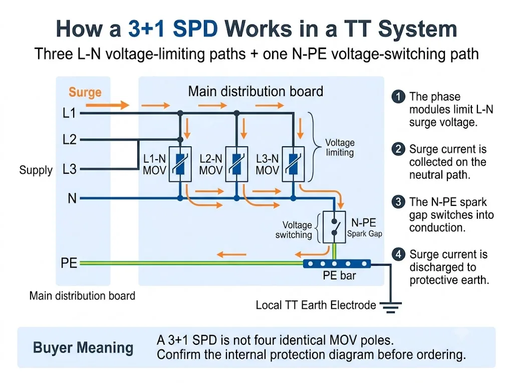
Untuk penjelasan tingkat sistem yang lebih luas, lihat Panduan SPD Sistem TT. Halaman ini tetap berfokus pada modul celah percikan N-PE dan makna pengadaannya.
3+1 vs 4+0: Apa Perubahannya di Dalam SPD?
Kedua pengaturan tersebut dapat dijual dalam rumah yang tampak memiliki empat kutub. Perbedaan pentingnya terletak pada topologi perlindungan internal.
Kolom yang paling penting adalah “Jalur perlindungan.” Kolom ini menunjukkan mengapa jumlah kutub saja tidak cukup.
| Pengaturan | Jalur perlindungan | Fungsi N-PE | Pembeli harus mengonfirmasi |
|---|---|---|---|
| 3+1 | L1-N, L2-N, L3-N ditambah N-PE | Jalur pembuangan akhir bersama dari netral ke arde | Teknologi N-PE, peringkat, dan data perakitan total |
| 4+0 | L1-PE, L2-PE, L3-PE dan N-PE, atau pengaturan konduktor-ke-PE lainnya yang dinyatakan | Salah satu dari empat jalur konduktor-ke-PE, bukan jalur umum “+1” | Sirkuit, teknologi, dan kesesuaian yang tepat untuk sistem pembumian |
Kesimpulan pengadaan: “3P+N,” “4P,” “3+1,” dan “4+0” tidak selalu digunakan secara konsisten di berbagai pasar. Mintalah diagram sirkuit internal.
Perbandingan terperinci mengenai konfigurasi empat kutub yang lengkap ada di bagian Panduan SPD 3P+N vs 4P. Untuk halaman ini, poin utamanya adalah bahwa SPD 3+1 memberikan peran pelepasan bersama yang spesifik pada modul N-PE.
Apa Fungsi Spark Gap di Jalur N-PE?
Celah percikan adalah elemen perlindungan pengalih tegangan. Komponen ini tetap sangat isolatif selama operasi normal. Ketika kondisi pengalihannya tercapai saat terjadi lonjakan arus, ia berubah dengan cepat menjadi kondisi konduktif.
Setelah lonjakan arus berlalu, SPD berbasis celah percikan AC mungkin juga perlu memadamkan arus yang disuplai oleh sistem daya. IEC 61643-01 dan IEC 61643-11 mencakup persyaratan mengenai SPD dan mode perlindungan dengan arus susulan.[1][2]
Dalam pemilihan N-PE praktis, tiga karakteristik memerlukan perhatian khusus:
- Isolasi tinggi antara netral dan arde selama pengoperasian normal
- Kemampuan arus lonjakan yang dinyatakan selama pengoperasian
- Perilaku TOV dan arus susulan dalam kondisi AC yang tidak normal
SPD Spark Gap N-PE vs Modul MOV Biasa
Celah percikan N-PE dan modul MOV tidak boleh dibandingkan seolah-olah keduanya adalah komponen yang dapat dipertukarkan. Keduanya menggunakan prinsip operasi yang berbeda dan biasanya melindungi jalur yang berbeda dalam konfigurasi 3+1.
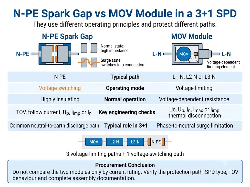
Bandingkan peran perlindungan terlebih dahulu. Peringkat arus saja tidak menunjukkan apakah dua modul menjalankan fungsi yang sama.
| Titik keputusan | Celah percikan N-PE | Modul MOV |
|---|---|---|
| Prinsip kerja | Pensaklaran tegangan | Pembatasan tegangan |
| Jalur 3+1 tipikal | N-PE | L1-N, L2-N or L3-N |
| Kondisi normal | Memiliki isolasi tinggi sebelum loncatan bunga api | Resistansi yang bergantung pada tegangan |
| Pemeriksaan utama AC | Perilaku TOV dan arus susulan | Stabilitas termal dan pemutusan |
| Penilaian kunci | Uc, Up, In atau Iimp, arus total jika dinyatakan | Uc, Up, In, Imax atau Iimp |
Kesimpulan pengadaan: tidak ada teknologi yang secara universal lebih baik. Kesesuaian bergantung pada jalur perlindungan, klasifikasi SPD, dan kinerja yang dinyatakan dari perakitan lengkap.
Untuk perbandingan yang lebih luas mengenai kedua teknologi operasi tersebut, lihat Panduan SPD Spark Gap vs MOV.
Apakah SPD Spark Gap N-PE Selalu Tipe 1?
Tidak. Teknologi celah percikan tidak secara otomatis menjadikan SPD lengkap sebagai perangkat Tipe 1.
Dokumentasi produk resmi menunjukkan penangkal arus petir N-PE Tipe 1 dan perangkat celah percikan N-PE Tipe 2. Klasifikasi harus dikonfirmasi dari deklarasi dan dokumentasi pengujian untuk SPD lengkap atau mode perlindungan yang dinyatakan.[2][5][6]
Perbedaan utamanya terletak pada klasifikasi pengujian yang dinyatakan, bukan pada tampilan visual kartrid N-PE.
| Barang | Jalur N-PE Tipe 1 | Jalur N-PE Tipe 2 |
|---|---|---|
| Uji impuls utama | Iimp dengan bentuk gelombang arus 10/350 µs | In dan umumnya Imax dengan bentuk gelombang arus 8/20 µs |
| Peran proyek umum | Penanganan arus petir pada titik masuk yang relevan | Pembatasan lonjakan arus dan perlindungan hilir yang terkoordinasi |
| Teknologi | Dapat menggunakan celah percikan | Dapat juga menggunakan celah percikan |
| Bukti persetujuan | Deklarasi Tipe 1 atau Tipe 1+2 lengkap | Lengkapi deklarasi Tipe 2 |
Peringatan pembeli: jangan menyimpulkan kinerja Tipe 1 hanya dari kata “celah percikan” (spark gap), “N-PE”, atau “proteksi petir”.
Bagaimana Modul N-PE Mempengaruhi Koordinasi RCD?
Instalasi TT umumnya menggunakan perangkat arus sisa sebagai bagian dari pengaturan proteksi gangguan. Oleh karena itu, posisi SPD dan pengaturan RCD perlu ditinjau secara bersamaan.
Jalur N-PE berbasis celah percikan biasanya memberikan isolasi yang sangat tinggi selama operasi normal. Hal ini dapat membantu menghindari jalur netral-ke-tanah yang konduktif secara terus-menerus atau mengalami tegangan terus-menerus.
Namun, lonjakan arus yang dilepaskan melalui SPD masih dapat memengaruhi RCD. Hasilnya bergantung pada posisi perangkat, karakteristik RCD, sistem pembumian, mode perlindungan SPD, dan pengaturan instalasi. IEC 61643-12 membahas pemilihan, lokasi, dan koordinasi SPD, sementara IEC 60364-5-53 menyediakan kerangka kerja instalasi yang harus diterapkan pada proyek yang sebenarnya.[3][4]
Detail instalasi, panjang sambungan, perlindungan cadangan, dan hubungan RCD dibahas lebih lengkap dalam Panduan Pemasangan SPD IEC 60364-5-534.
Parameter N-PE Apa yang Harus Diverifikasi Pembeli?
1. Mode perlindungan yang dinyatakan
Lembar data atau diagram sirkuit harus mengidentifikasi jalur N-PE dengan jelas. Jangan menyimpulkan mode perlindungan dari warna kartrid atau posisinya di dalam rumah perangkat.
2. Tegangan operasi kontinu maksimum, Uc
Konfirmasikan Uc yang dinyatakan untuk jalur N-PE. Nilainya mungkin tidak sama dengan yang digunakan untuk modul fase L-N.
3. Tingkat perlindungan tegangan, Up
Periksa nilai Up yang dinyatakan untuk N-PE serta tingkat perlindungan dari mode atau rakitan lengkap. IEC 61643-01 dan IEC 61643-11 membedakan pengujian SPD lengkap, mode perlindungan, dan rakitan SPD.[1][2]
4. Iimp, In, dan Imax
Untuk kinerja Tipe 1, verifikasi Iimp menggunakan bentuk gelombang 10/350 µs. Untuk kinerja Tipe 2, verifikasi In dan, jika dinyatakan, Imax menggunakan bentuk gelombang 8/20 µs.
5. Kapasitas pengosongan total
Beberapa produk 3+1 menyatakan arus total untuk susunan lengkap atau jalur N-PE bersama. Jangan tertukar dengan nilai peringkat satu kartrid L-N.
6. Perilaku tegangan lebih sementara (TOV)
TOV adalah tegangan lebih frekuensi daya yang berlangsung jauh lebih lama daripada impuls lonjakan. Pastikan apakah produk tersebut tahan terhadap kondisi yang dinyatakan atau memasuki mode kegagalan aman yang telah ditentukan. Data TOV khusus produk harus diambil dari dokumentasi model yang tepat.[7][8]
7. Kemampuan pemadaman arus susulan
Jika arus susulan relevan dan dinyatakan, konfirmasikan kemampuan pemadaman celah percikan N-PE. Jangan berasumsi bahwa setiap desain celah percikan memiliki perilaku yang sama.[2][8]
8. Perlindungan cadangan dan data hubungan arus pendek
Konfirmasikan sekering atau pemutus sirkuit hulu yang diperlukan serta kemampuan hubungan arus pendek dari SPD secara keseluruhan. Jangan memilih perlindungan cadangan hanya berdasarkan nilai satu kartrid.
9. Penggantian, indikasi status, dan pensinyalan jarak jauh
Periksa apakah elemen N-PE dapat diganti, apakah memiliki indikasi status visual, dan apakah kontak jarak jauh memantau keseluruhan unit.
Bagaimana Memverifikasi SPD 3+1 Sebelum Persetujuan OEM atau Proyek
Proses pembelian yang paling aman adalah dengan mengonfirmasi sistem terlebih dahulu, kemudian pengaturan perlindungan internal, dan setelah itu baru menyetujui peringkat kelistrikan serta model fisik.
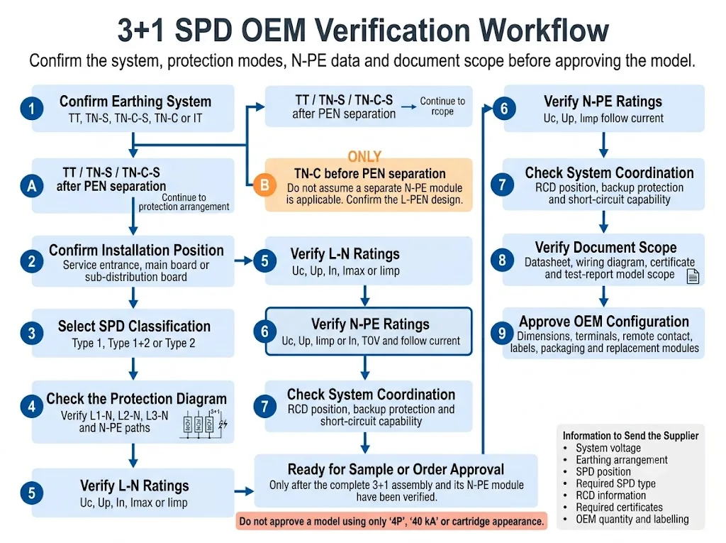
- Konfirmasi sistem penyaluran. Identifikasi apakah instalasi tersebut bertipe TT, TN-S, TN-C-S, TN-C, atau IT. Untuk TN-C-S, nyatakan apakah SPD dipasang sebelum atau sesudah pemisahan PEN.
- Konfirmasi posisi instalasi. Nyatakan apakah SPD berada di pintu masuk layanan, papan distribusi utama, atau papan distribusi hilir.
- Pilih klasifikasi SPD yang diperlukan. Pastikan apakah proyek tersebut memerlukan kinerja Tipe 1, Tipe 1+2, atau Tipe 2.
- Verifikasi sirkuit internal. Konfirmasikan pengaturan 1+1, 3+1, 4+0, atau pengaturan lain yang dinyatakan dalam diagram pengkabelan.
- Periksa jalur L-N dan N-PE secara terpisah. Verifikasi Uc, Up, dan peringkat arus pelepasan yang berlaku untuk setiap komponen.
- Tinjau perilaku TOV dan arus ikutan. Gunakan lembar data model yang tepat. Jangan mengganti nilai dari produk yang terlihat serupa.
- Periksa koordinasi sistem. Konfirmasi posisi RCD, perlindungan cadangan, dan persyaratan hubungan arus pendek.
- Verifikasi cakupan dokumen. Pastikan lembar data, sertifikat, laporan pengujian, dan petunjuk pemasangan mencakup perakitan lengkap yang sebenarnya.
- Setujui konfigurasi OEM. Konfirmasikan dimensi, terminal, kontak jarak jauh, pengodean kartrid, label, kemasan, dan referensi penggantian.
Bukti Apa yang Harus Mendukung Persetujuan Proyek?
Grafik teknis menjelaskan sirkuit, namun persetujuan proyek harus didasarkan pada bukti khusus model. Pembeli harus meminta dokumen yang mengidentifikasi perakitan yang tepat beserta modul N-PE-nya.
Menunjukkan apakah produk lengkap tersebut merupakan konfigurasi perlindungan 3+1, 4+0, atau pengaturan lainnya.
Mencantumkan peringkat L-N dan N-PE, data TOV, tingkat perlindungan, dan persyaratan cadangan.
Mengonfirmasi model, konfigurasi, dan edisi standar mana yang sebenarnya tercakup.
Menentukan terminal yang disetujui, pengaturan konduktor, perlindungan cadangan, dan proses penggantian.
Rekomendasi model LEEYEE harus dikonfirmasi dengan lembar data spesifik model, gambar, dan dokumen kesesuaian yang tersedia saat ini sebelum pengambilan sampel atau persetujuan pesanan. CNSPD adalah platform LEEYEE yang berfokus pada perlindungan lonjakan arus untuk pembeli teknis global.
Kesalahan Umum Saat Memesan N-PE atau SPD 3+1
Pemesanan hanya dengan “4P”
Empat modul yang terlihat tidak membuktikan bahwa produk tersebut menggunakan sirkuit 3+1.
Menganggap keempat modul tersebut identik
Celah percikan N-PE mungkin menggunakan teknologi dan parameter yang berbeda dari ketiga modul L-N.
Mengasumsikan setiap celah percikan adalah Tipe 1
Produk celah percikan N-PE Tipe 2 juga tersedia. Pastikan klasifikasi SPD secara lengkap.[6]
Hanya membandingkan Imax
Imax saja tidak menjelaskan kemampuan Tipe 1, perilaku TOV, arus susulan, tingkat perlindungan tegangan, atau peringkat rakitan 3+1 secara keseluruhan.
Mengabaikan posisi RCD
SPD yang sama dapat berinteraksi secara berbeda dengan instalasi tergantung pada jenis RCD, lokasi, dan pengaturan pengkabelan.
Mengganti kartrid berdasarkan tampilan
Rumah yang serupa mungkin memiliki nilai Uc, pengodean, mode perlindungan, atau kompatibilitas dasar yang berbeda.
Memeriksa dokumen hanya untuk satu modul
Lembar data kartrid tidak secara otomatis membuktikan bahwa rakitan 3+1 lengkap memiliki cakupan pengujian atau sertifikat yang diperlukan.
Sebelum Memesan, Siapkan Detail Ini
- Tegangan dan frekuensi sistem nominal
- Sistem TT, TN-S, TN-C-S, TN-C, atau IT
- Posisi pemasangan SPD
- Klasifikasi Tipe 1, Tipe 1+2, atau Tipe 2 yang diperlukan
- Pengaturan 1+1, 3+1, 4+0, atau pengaturan lainnya yang diperlukan
- Nilai Uc L-N dan N-PE
- Nilai Up L-N dan N-PE
- Iimp, In, Imax atau arus total yang diperlukan
- Perilaku TOV N-PE
- Ikuti persyaratan arus jika berlaku
- Informasi sekering cadangan atau pemutus sirkuit
- Tipe RCD dan posisi pemasangan
- Persyaratan sinyal jarak jauh
- Lebar rel DIN dan pengaturan terminal
- Standar yang dipersyaratkan dan cakupan sertifikat
- Label OEM, kemasan, kuantitas, dan modul pengganti
Konfirmasi Konfigurasi SPD N-PE atau 3+1
Kirimkan tegangan sistem, pengaturan pembumian, posisi pemasangan, tipe SPD yang diperlukan, informasi RCD, diagram perlindungan, dan persyaratan arus pelepasan.
LEEYEE dapat menggunakan detail ini untuk meninjau konfigurasi yang diminta dan menyiapkan rekomendasi model untuk papan distribusi, pasokan proyek, atau persetujuan OEM. Pemilihan akhir tetap bergantung pada desain proyek, aturan yang berlaku, dan dokumentasi khusus model.
Konfirmasi Konfigurasi SPD OEMFAQ Tentang SPD Spark Gap N-PE
Apa arti N-PE pada SPD?
N-PE mengidentifikasi jalur perlindungan lonjakan arus antara netral dan pembumian pelindung. Pada banyak produk 3+1, jalur ini menggunakan celah percikan pengalih tegangan.
Mengapa celah percikan N-PE digunakan dalam SPD 3+1?
Jalur N-PE menjalankan fungsi yang berbeda dari ketiga jalur L-N. Jalur ini menyediakan rute pembuangan netral-ke-ground bersama sekaligus tetap sangat isolatif selama pengoperasian normal.
Apakah SPD 3+1 sama dengan SPD empat kutub mana pun?
Tidak. Produk empat kutub dapat menggunakan konfigurasi 3+1, 4+0, atau pengaturan lain yang dinyatakan. Diagram sirkuit internal diperlukan.
Apakah setiap celah percikan N-PE merupakan perangkat Tipe 1?
Tidak. Dokumentasi produk resmi menunjukkan adanya penangkal arus petir N-PE Tipe 1 dan perangkat celah percikan N-PE Tipe 2.[5][6]
Bisakah modul MOV menggantikan kartrid celah percikan N-PE?
Tidak bisa tanpa persetujuan teknis. Prinsip operasi, mode perlindungan, perilaku TOV, perilaku arus susulan, dan koordinasi perakitan secara keseluruhan mungkin berbeda.
Apakah celah percikan N-PE dapat mencegah gangguan pemicuan RCD?
Perangkat ini dapat memberikan isolasi tinggi selama pengoperasian normal, namun tidak dapat menjamin bahwa RCD tidak akan pernah beroperasi. Koordinasi bergantung pada posisi SPD, karakteristik RCD, dan pengaturan instalasi.
Apakah modul N-PE harus memiliki peringkat arus yang sama dengan modul fase?
Tidak secara otomatis. Jalur N-PE bersama dapat dinyatakan menggunakan data spesifik jalur atau data arus total yang berbeda. Gunakan dokumentasi perakitan yang lengkap.
Dokumen apa saja yang harus diminta oleh pembeli OEM?
Minta diagram sirkuit, lembar data spesifik model, petunjuk pemasangan, informasi perlindungan cadangan, cakupan sertifikat atau laporan pengujian, gambar dimensi, dan referensi modul pengganti.
Referensi
- Komisi Elektroteknik Internasional, IEC 61643-01:2024, Perangkat pelindung lonjakan arus tegangan rendah — Bagian 01: Persyaratan umum dan metode pengujian. Halaman publikasi resmi IEC.
- Komisi Elektroteknik Internasional, IEC 61643-11:2025, Perangkat pelindung lonjakan arus tegangan rendah — Bagian 11: Perangkat pelindung lonjakan arus yang terhubung ke sistem daya tegangan rendah AC — Persyaratan dan metode pengujian. Halaman publikasi resmi IEC.
- Komisi Elektroteknik Internasional, IEC 61643-12:2020, Perangkat pelindung lonjakan arus tegangan rendah — Bagian 12: Perangkat pelindung lonjakan arus yang terhubung ke sistem daya tegangan rendah — Prinsip pemilihan dan penerapan. Halaman publikasi resmi IEC.
- Komisi Elektroteknik Internasional, IEC 60364-5-53:2019+AMD1:2020+AMD2:2024 CSV, Instalasi listrik tegangan rendah — Bagian 5-53: Pemilihan dan pemasangan peralatan listrik — Perangkat untuk perlindungan demi keselamatan, isolasi, penyaklaran, kontrol, dan pemantauan. Halaman publikasi resmi IEC.
- DEHN, Penangkap Arus Petir N-PE, informasi aplikasi dan kategori produk resmi untuk penangkap N-PE Tipe 1 berbasis celah percikan yang digunakan dalam konfigurasi 3+1 dan 1+1. Halaman resmi DEHN.
- Phoenix Contact, VAL-ME-N/PE — Perangkat Pelindung Lonjakan Arus Tipe 2, informasi produk resmi yang mengidentifikasi arrester Tipe 2 sebagai celah percikan N-PE. Halaman resmi Phoenix Contact.
- OBO Bettermann, Penangkal Petir V20, Bebas Arus Bocor, 3-Kutub + NPE, data produk dan TOV resmi spesifik model. Halaman resmi OBO.
- OBO Bettermann, Penangkal Petir V20 dengan Sekring Awal Terintegrasi, 3+NPE, TOV spesifik model resmi, perlindungan cadangan, dan data arus susulan N-PE. Halaman resmi OBO.
