
Sebuah SPD mungkin bertahan dari impuls petir yang sangat tinggi tetapi gagal selama tegangan yang jauh lebih rendah yang tetap ada selama beberapa detik atau lebih. Tegangan abnormal yang lebih lama ini disebut sebagai overvoltage sementara, atau TOV.
Untuk pembeli OEM dan pembangun panel, ketahanan TOV adalah parameter risiko pengadaan. Ini membantu menentukan apakah SPD dapat tetap stabil, terputus dengan cara yang terkontrol, atau mengalami kerusakan serius ketika tegangan sistem meningkat melebihi rentang operasi kontinu yang dimaksudkan.
Daftar Isi
Apa itu ketahanan SPD TOV?
Lonjakan adalah peristiwa transien singkat yang dimaksudkan untuk dibatasi oleh SPD. TOV adalah tegangan frekuensi daya atau DC abnormal yang bertahan cukup lama untuk menciptakan stres listrik dan termal yang berkelanjutan.[1][2][4]
Tahanan TOV bukanlah angka tegangan tunggal. Pernyataan yang berarti harus mengidentifikasi mode perlindungan, tegangan yang diterapkan, durasi, dan hasil yang diharapkan.
- Uc atau Ucpv mencakup tegangan berkelanjutan. Tegangan operasi nyata harus tetap dalam batas yang dinyatakan.
- UT mendeskripsikan kondisi abnormal yang telah ditentukan. Ini harus dibaca bersama dengan durasi dan hasil pengujian.
- Uc yang rendah dapat meningkatkan sensitivitas TOV. Konduksi MOV yang berkelanjutan dapat menyebabkan pemanasan dan pemutusan.
- Imax yang tinggi tidak membuktikan kekuatan TOV. Risiko arus impuls dan tegangan berkelanjutan adalah berbeda.
Keputusan Persetujuan Cepat untuk Pembeli
Gunakan tabel ini sebelum menyetujui sampel, item BOM, atau model label pribadi. Ini adalah alat penyaringan, bukan pengganti rekayasa proyek.
| Keputusan | Temuan | Tindakan yang diperlukan |
|---|---|---|
| Setujui | Data model yang tepat cocok dengan tegangan sistem, mode perlindungan, kondisi TOV dan persyaratan hubungan pendek. | Lanjutkan ke persetujuan sampel atau BOM, tergantung pada tinjauan proyek yang lengkap. |
| Tahan | UT ditampilkan tanpa durasi, hasil kegagalan yang aman tidak jelas, atau ruang lingkup sertifikat tidak mengidentifikasi model yang tepat. | Minta kondisi uji yang hilang, ruang lingkup laporan, dan informasi instalasi. |
| Tolak | Tegangan maksimum normal melebihi Uc atau Ucpv, jenis aplikasi salah, atau mode perlindungan yang diperlukan tidak didukung. | Pilih model lain atau koreksi spesifikasi sistem sebelum melakukan pemesanan. |
Sebuah produk tidak boleh disetujui hanya berdasarkan label depan, nilai Imax, atau pernyataan umum “tahan TOV”.
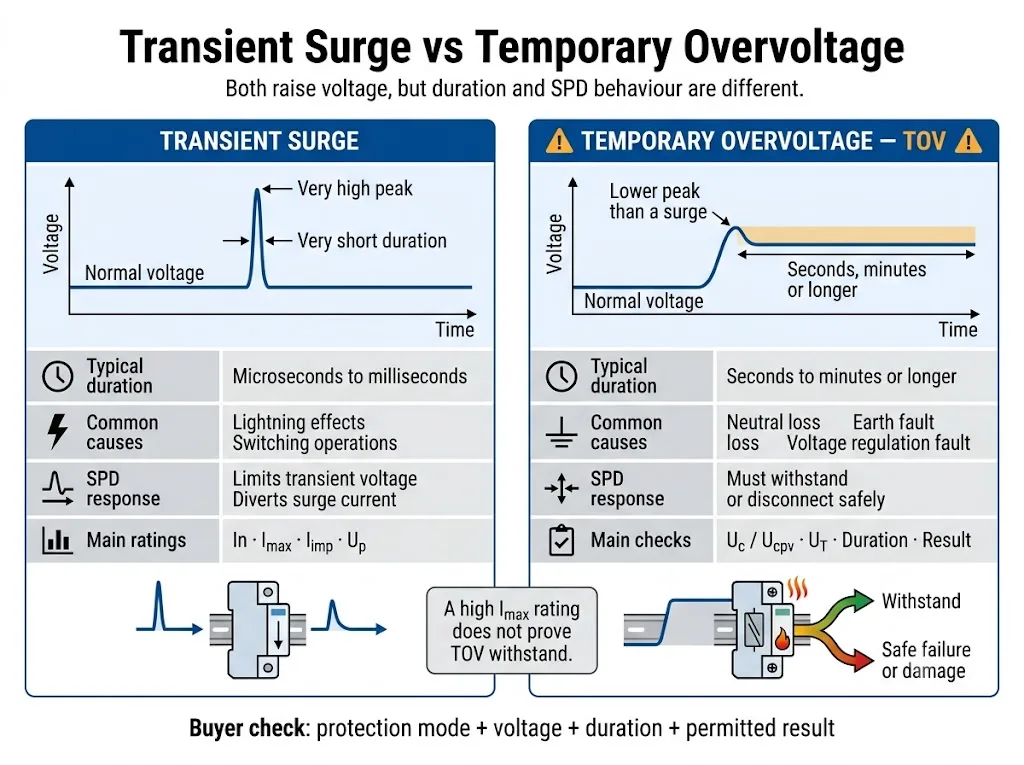
TOV dan Lonjakan adalah Peristiwa Listrik yang Berbeda
Kedua peristiwa meningkatkan tegangan di atas tingkat normalnya. Perbedaan penting adalah durasi, sumber energi, dan cara SPD merespons.
| Perbandingan | Lonjakan transien | Overvoltage sementara |
|---|---|---|
| Sifat | Sebuah impuls tegangan atau arus singkat dengan puncak yang tinggi. | Tegangan AC RMS atau DC yang abnormal yang tetap ada. |
| Penyebab yang mungkin | Dampak petir, pemutusan beban induktif dan switching. | Kehilangan netral, kesalahan tanah, regulasi yang buruk, tegangan pasokan yang salah atau kesalahan sumber. |
| Fungsi SPD | Membatasi tegangan transien dan mengalihkan arus impuls. | Harus tetap stabil atau memasuki kondisi akhir masa pakai yang terkendali yang dinyatakan. |
| Rating utama | In, Imax, Iimp dan Up. | Uc atau Ucpv, UT, mode perlindungan, durasi dan hasil. |
| Risiko utama | Energi impuls berlebih atau stres lonjakan yang terakumulasi. | Konduksi berkelanjutan, pemanasan, pelarian termal atau kelanjutan arus kesalahan. |
Standar yang berlaku dan dokumentasi produk menentukan durasi uji TOV yang tepat. Jangan menerapkan satu ambang waktu universal untuk setiap sistem atau SPD.
Empat Bidang Diperlukan untuk Memahami Peringkat TOV
Pernyataan seperti “resistansi TOV tinggi” atau “SPD tahan TOV” bukanlah data teknik yang lengkap. Pembeli membutuhkan empat bidang khusus.
| Bidang yang diperlukan | Apa artinya | Dampak pengadaan |
|---|---|---|
| Mode perlindungan | Dua konduktor tempat tegangan abnormal diterapkan. | Jalur L-N, L-PE dan N-PE dapat mengalami tegangan kesalahan yang berbeda. |
| Tegangan yang diterapkan | Tegangan uji AC RMS atau DC TOV yang ditentukan, sering diidentifikasi sebagai UT. | Bandingkan dengan tegangan abnormal yang kredibel dalam sistem yang sebenarnya. |
| Durasi | Seberapa lama tegangan abnormal diterapkan selama kondisi yang dinyatakan. | Sebuah SPD mungkin dapat bertahan dari satu tegangan untuk sementara waktu tetapi terputus selama paparan yang lebih lama. |
| Hasil | Perilaku yang diperlukan setelah atau selama pengujian. | Tentukan apakah SPD tetap berfungsi, terputus, atau memerlukan penggantian. |
Uc, Ucpv dan UT Tidak Berarti Hal yang Sama
Uc adalah tegangan maksimum yang dapat diterapkan secara terus-menerus pada mode perlindungan SPD yang dinyatakan. Ucpv adalah parameter yang sesuai digunakan untuk SPD fotovoltaik.[1][2][6]
UT menggambarkan perilaku selama kondisi tegangan abnormal sementara tertentu. Uc atau Ucpv dan UT saling berkaitan, tetapi keduanya tidak dapat saling menggantikan.
| Parameter | Pertanyaan terjawab | Risiko persetujuan |
|---|---|---|
| Un atau Uo | Berapa tegangan nominal sistem atau fasa-ke-netral? | Ini adalah titik awal, bukan nilai pemilihan tegangan SPD yang final. |
| Uc | Dapatkah SPD tetap terhubung secara terus-menerus pada tegangan ini? | Nilai yang terlalu rendah dapat meningkatkan kebocoran, pemanasan, dan pelepasan dini. |
| Ucpv | Dapatkah SPD PV tetap terhubung pada tegangan maksimum array yang dihitung? | Tegangan operasi normal inverter saja tidak cukup. |
| UT | Apa yang terjadi pada tegangan dan durasi abnormal yang dinyatakan? | Nilai tegangan tanpa durasi dan hasil adalah tidak lengkap. |
| Naik | Berapa tingkat proteksi tegangan yang dinyatakan selama uji surja yang ditentukan? | Uc yang lebih tinggi tidak secara otomatis memberikan koordinasi proteksi yang paling sesuai. |
Mengapa Uc yang Rendah Dapat Menyebabkan Kegagalan?
Sebagian besar SPD catu daya AC pembatas tegangan menggunakan satu atau lebih varistor logam oksida. Pada tegangan normal, MOV hanya membawa arus bocor yang kecil.
Ketika tegangan yang diterapkan meningkat melampaui rentang operasi stabil komponen, arus MOV dapat meningkat tajam. Jika tegangan abnormal tetap berlangsung, energi listrik diubah menjadi panas, alih-alih ditangani sebagai satu impuls surja singkat.[9]
Apakah Uc yang Lebih Tinggi Selalu Lebih Baik?
Tidak. Uc yang lebih tinggi dapat meningkatkan margin tegangan kontinu, tetapi SPD yang dipilih tetap harus memberikan Up, mode proteksi, dan koordinasi yang sesuai dengan peralatan yang dilindungi.
Pilihan yang tepat bukan sekadar Uc tertinggi yang tersedia. Yang dibutuhkan adalah nilai yang secara aman mencakup tegangan operasi maksimum yang sebenarnya dan kondisi gangguan yang kredibel, sambil memenuhi tingkat proteksi yang disyaratkan.[3]
Bagaimana TOV Dapat Membuat SPD Panas, Terputus, atau Terbakar?
Respons yang tepat bergantung pada teknologi SPD, konstruksi internal, dan gangguan pada sistem. Urutan kegagalan umum berbasis MOV ditunjukkan di bawah ini.
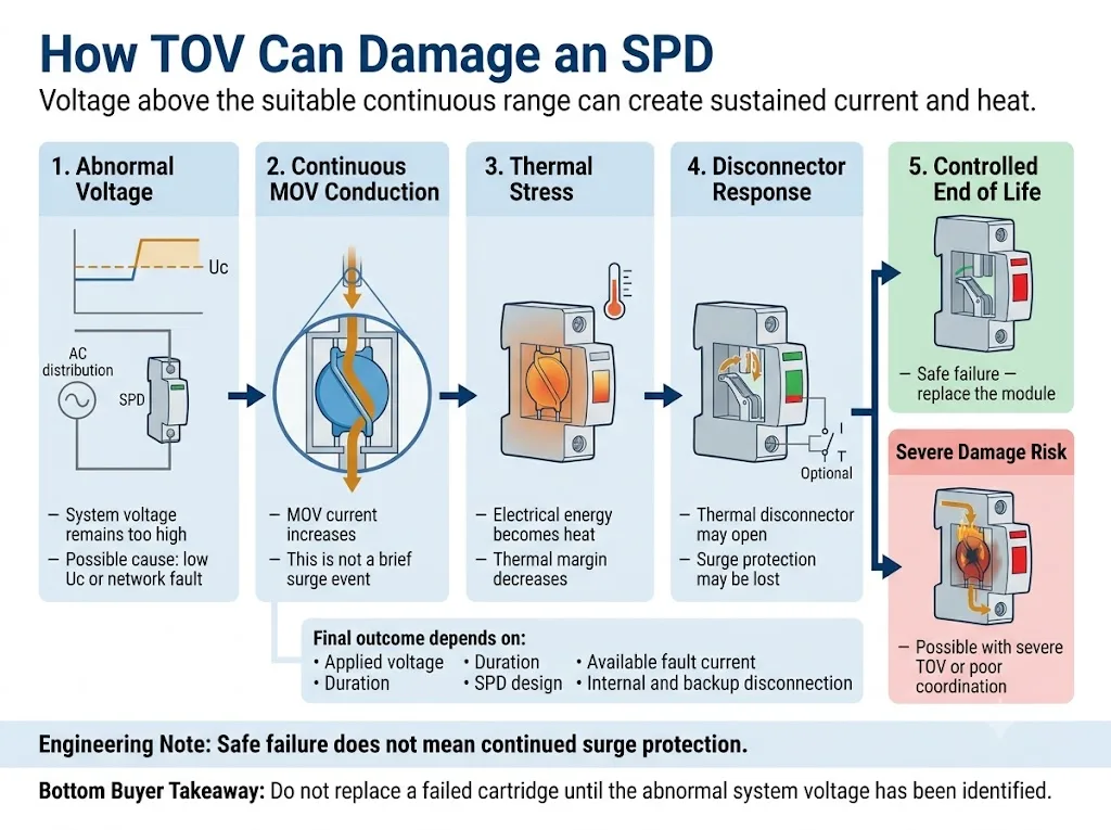
- Tegangan yang diterapkan melebihi rentang kontinu yang sesuai. Hal ini dapat disebabkan oleh pemilihan Uc yang terlalu rendah atau kondisi sistem yang abnormal.
- Komponen pembatas tegangan menghantarkan arus secara terus-menerus. SPD menyerap arus frekuensi daya atau arus DC, bukan menangani satu impuls singkat.
- Suhu internal meningkat. Masukan energi yang berkelanjutan mengurangi sisa margin termal.
- Pemutus termal dapat terbuka. Pemutusan yang terkontrol dapat mengisolasi komponen yang terbebani dan mengubah status indikator.
- Kerusakan parah tetap mungkin terjadi. TOV yang berat, arus gangguan yang tersedia tinggi, atau pemutusan yang tidak memadai dapat memperbesar kegagalan.
Penelitian TOV yang diselenggarakan NIST menemukan bahwa respons SPD terhadap tegangan abnormal yang berkelanjutan dapat berkisar dari tanpa kerusakan hingga kehancuran total. Makalah tersebut mengidentifikasi tegangan operasi kontinu maksimum dan respons pemutus sebagai faktor penting dalam kerentanan terhadap TOV.[9]
TOV Harus Diperiksa untuk Setiap Mode Perlindungan
SPD multipolar tidak terpapar pada satu tegangan tunggal. Setiap elemen proteksi menerima tegangan antara dua konduktor yang terhubung ke jalur proteksi tersebut.
| Mode perlindungan | Pertanyaan pemilihan normal | Risiko TOV untuk dikonfirmasi |
|---|---|---|
| L-N | Berapa tegangan fasa-ke-netral kontinu maksimum? | Kehilangan netral, sambungan netral yang buruk, dan ketidakseimbangan beban. |
| L-PE | Tegangan apa yang dapat muncul antara penghantar fasa dan tanah? | Gangguan tanah, pergeseran netral, dan perilaku sistem pentanahan. |
| N-PE | Teknologi dan rating proteksi N-PE apa yang digunakan? | Tegangan netral-ke-tanah sementara selama kondisi gangguan tanah tertentu. |
| DC +/− | Berapakah tegangan DC kutub-ke-kutub maksimum? | Tegangan pengisian daya, kesalahan regulasi, dan konfigurasi sirkuit yang tidak tepat. |
| Kutub DC-PE | Bagaimana sistem DC direferensikan ke arde? | Gangguan tanah dapat menggeser tegangan di sepanjang jalur perlindungan kutub-ke-tanah. |
Mengapa Kehilangan Netral Merupakan Skenario TOV AC yang Kritis
Dalam sistem empat kawat tiga fase 230/400 V yang normal, jalur perlindungan L-N biasanya menerima tegangan sekitar 230 V.
Jika konduktor netral terputus atau mengalami impedansi tinggi, titik netral tidak lagi stabil. Dengan beban satu fase yang tidak seimbang, beberapa tegangan L-N dapat turun sementara yang lain naik secara signifikan dan mungkin mendekati tegangan antar-fasa 400 V.[4][9]
Kondisi Pasokan Sehat versus Kehilangan Netral
SPD dengan Uc 275 V mungkin cocok untuk sirkuit L-N 230 V yang stabil jika persyaratan sistem dan produk secara keseluruhan telah terpenuhi.
Jika kehilangan netral menyebabkan jalur perlindungan yang sama mengalami tegangan berkelanjutan yang jauh lebih tinggi, SPD mungkin mulai menghantarkan arus secara terus-menerus. Ketahanan, pemutusan yang aman, atau potensi kerusakan perangkat harus dipastikan berdasarkan data TOV dari model yang tepat.
Contoh ini tidak membuktikan bahwa setiap peristiwa kehilangan netral menghasilkan tepat 400 V. Tegangan aktual bergantung pada beban yang terhubung, pengaturan jaringan, dan kondisi gangguan.
Gangguan Pembumian dan Pengaturan Pembumian
Sistem TN-S, TN-C-S, TT, dan IT dapat memberikan tegangan sementara yang berbeda pada jalur perlindungan L-N, L-PE, dan N-PE. Tekanan aktual bergantung pada pengaturan instalasi dan kondisi gangguan.[3][4]
Hal ini sangat penting saat membandingkan sirkuit 4+0 dan 3+1. Modul L-N dan elemen N-PE menjalankan fungsi yang berbeda dan tidak boleh dianggap memiliki perilaku TOV yang identik.
Generator, Transformator, dan Jaringan Listrik Tidak Stabil
Kesalahan pengaturan generator, kesalahan tap transformator, penolakan beban, feroresonansi, dan regulasi utilitas yang buruk dapat menyebabkan tegangan abnormal yang berkelanjutan.
Untuk proyek-proyek ini, mintalah catatan tegangan terukur atau toleransi tegangan desain. Tegangan nominal saja tidak cukup untuk persetujuan Uc akhir.
Persyaratan tingkat instalasi dan kondisi TOV spesifik sistem harus diperiksa terhadap edisi IEC 60364 yang berlaku dan kode kelistrikan setempat. Terkait hal tersebut, Panduan pemasangan SPD IEC 60364-5-534 menjelaskan pemeriksaan instalasi yang lebih luas.
Cara Membaca Entri Lembar Data TOV yang Nyata
Contoh berikut menggunakan nilai-nilai yang dipublikasikan dalam panduan teknis produsen pihak ketiga. Hal ini hanya menjelaskan metode pembacaan. Ini bukan rekomendasi untuk model LEEYEE dan tidak boleh diterapkan pada produk lain tanpa verifikasi.[10]
| Entri yang diterbitkan | Interpretasi yang tepat | Asumsi keliru yang harus dihindari |
|---|---|---|
| Uc 275 V | Tegangan operasi kontinu maksimum yang dinyatakan untuk mode perlindungan yang disebutkan. | Produk ini dapat beroperasi secara terus-menerus pada setiap tegangan di bawah nilai UT tertingginya. |
| UT 337 V / 5 s | Kondisi TOV durasi singkat dengan hasil yang dinyatakan dalam dokumentasi produk yang sama. | 337 V adalah peringkat tegangan operasi kontinu lainnya. |
| UT 442 V / 120 min | Kondisi durasi lebih lama yang dikaitkan dengan hasil kegagalan aman yang dinyatakan. | SPD terus memberikan perlindungan secara normal selama dua jam pada tegangan 442 V. |
| Nilai N-PE terpisah | Kondisi TOV yang secara khusus ditetapkan untuk elemen perlindungan N-PE. | Nilai yang sama berlaku secara otomatis untuk elemen L-N dan L-PE. |
Apa yang Harus Diverifikasi pada Model LEEYEE?
Jangan berasumsi bahwa contoh pihak ketiga mewakili produk LEEYEE. Mintalah lembar data model LEEYEE yang tepat, diagram koneksi, serta cakupan pengujian atau sertifikat yang berlaku untuk konfirmasi proyek.
Bukti Spesifik Model untuk Diminta
- Label produk dan kartrid yang tepat
- Uc atau Ucpv untuk mode perlindungan yang dinyatakan
- Tegangan UT, durasi, dan hasil yang dideklarasikan
- Pengoperasian jendela status visual
- Informasi kontak pensinyalan jarak jauh
- Persyaratan pemutusan hubungan internal dan eksternal
- Peringkat ISCCR atau ISCPV jika berlaku
- Persyaratan sekering cadangan atau MCB
- Petunjuk pemasangan dan pengabelan
- Cakupan laporan atau sertifikat khusus model
- Gambar persetujuan label dan kemasan OEM
- Catatan inspeksi dan persetujuan sampel
Bukti harus ditinjau pada tingkat model yang tepat. Sertifikat, laporan, atau lembar data untuk satu versi tegangan atau konfigurasi kutub tidak boleh dianggap mencakup versi atau konfigurasi lainnya.
Apakah Kesimpulan TOV AC Berlaku Langsung untuk SPD DC atau PV?
Tidak. Sirkuit DC umum dan PV surya memerlukan perhitungan tegangan, mode perlindungan, dan standar produk yang terpisah.
IEC 61643-41:2025 mencakup SPD yang terhubung ke sirkuit daya tegangan rendah DC umum. SPD PV tetap berada dalam lingkup IEC 61643-31, dengan prinsip pemilihan yang dibahas dalam IEC 61643-32.[5][6][7]
Gunakan panduan terpisah panduan pemilihan Ucpv SPD DC dan PV untuk proses pemilihan tegangan PV yang lengkap.
Alur Kerja Verifikasi TOV SPD untuk Persetujuan OEM
Pastikan sistem kelistrikan sebelum menyetujui SPD. Alur kerja di bawah ini menjaga data sistem, peringkat produk, dan dokumen persetujuan tetap terhubung.
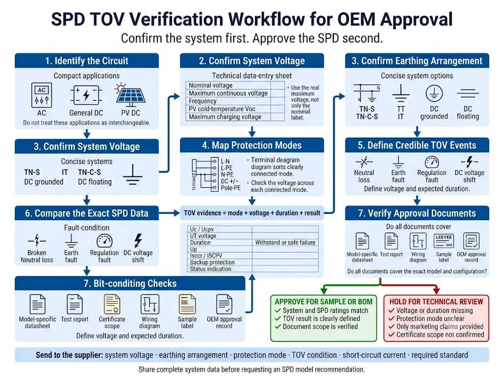
- Identifikasi sirkuit tersebut. Pisahkan aplikasi listrik AC utama, DC umum, dan PV surya. Rumah pelindung yang serupa tidak membuat produk tersebut dapat dipertukarkan.
- Konfirmasikan tegangan operasi maksimum yang sebenarnya. Sertakan toleransi suplai, perilaku generator atau transformator, tegangan pengisian daya, atau tegangan suhu dingin PV.
- Konfirmasikan pengaturan pembumian. Catat TN-S, TN-C-S, TT, IT, atau metode pembumian DC yang relevan.
- Petakan setiap mode perlindungan. Periksa jalur L-N, L-PE, N-PE, kutub-ke-kutub, dan kutub-ke-bumi sebagaimana mestinya.
- Definisikan peristiwa TOV yang kredibel. Tinjau kehilangan netral, gangguan bumi, gangguan regulasi, dan kondisi abnormal spesifik sumber.
- Bandingkan data SPD secara lengkap. Tinjau Uc atau Ucpv, UT, durasi, hasil, Up, peringkat arus pendek, dan pengaturan pemutusan.
- Verifikasi cakupan dokumen persetujuan. Pastikan lembar data, laporan, dan sertifikat sesuai dengan versi tegangan, konfigurasi kutub, dan model yang dipesan secara tepat.
Informasi yang Harus Dikirim Sebelum Meminta Rekomendasi Model
- Tegangan nominal sistem
- Tegangan kontinu maksimum
- Aplikasi AC, DC umum, atau PV
- Frekuensi sistem jika berlaku
- Pengaturan pentanahan atau arde
- Mode perlindungan yang diperlukan
- Skenario kehilangan netral atau gangguan tanah
- Uc atau Ucpv yang sedang dipertimbangkan
- Tegangan dan durasi TOV yang diperlukan
- Hasil ketahanan atau kegagalan aman yang diperlukan
- Arus hubung singkat prospek
- Informasi sekering cadangan atau MCB
- Standar atau sertifikat yang diperlukan
- Persyaratan sinyal jarak jauh
- Kuantitas dan posisi pemasangan
- Label OEM atau persyaratan pengemasan
Konfirmasi Data TOV Sebelum Menyetujui Model SPD
Kirimkan tegangan sistem, pengaturan pembumian, mode perlindungan, dan kondisi tegangan abnormal yang kredibel. LEEYEE dapat membantu mengidentifikasi data Uc, Ucpv, dan TOV mana yang harus diverifikasi sebelum persetujuan sampel atau BOM.
CNSPD adalah platform LEEYEE yang berfokus pada perlindungan lonjakan arus untuk pembeli teknis global. Dirancang untuk Melindungi. Dipercaya untuk Bertahan.
Bagikan Detail Sistem Anda untuk DitinjauApa yang Harus Diperiksa Setelah Peristiwa TOV yang Diduga?
Jangan memasang kartrid pengganti sebelum mengidentifikasi tegangan abnormal yang asli. SPD baru dapat mengalami kegagalan kembali jika kesalahan sistem masih ada.
- Isolasi sirkuit sesuai dengan prosedur keselamatan kelistrikan di lokasi.
- Catat indikator SPD, alarm jarak jauh, dan label produk secara lengkap.
- Ukur tegangan L-N, L-L, L-PE, N-PE, atau kutub DC sebagaimana mestinya.
- Periksa kontinuitas netral, pembumian, dan diagram satu garis yang berlaku.
- Inspeksi kartrid, basis, konduktor, terminal, dan perlindungan cadangan.
- Tinjau catatan generator, transformator, inverter, relai, dan peristiwa utilitas.
- Konfirmasi data penggantian Uc, Ucpv, TOV serta konfigurasi perlindungannya.
Untuk proses diagnostik yang lebih luas, gunakan panduan terkait panduan penyebab kegagalan SPD.
Pertanyaan yang Sering Diajukan tentang Ketahanan SPD TOV
Dapatkah SPD melindungi peralatan dari tegangan lebih sementara?
SPD terutama ditujukan untuk membatasi tegangan lebih transien. Perangkat ini biasanya tidak mengatur atau menghilangkan tegangan sistem abnormal yang berkelanjutan. Selama TOV, perangkat mungkin tetap stabil atau memasuki kondisi akhir masa pakai terkendali yang telah ditetapkan.
Dapatkah TOV menyebabkan SPD terbakar?
Ya. Konduksi yang berkelanjutan dapat menyebabkan panas berlebih, pelarian termal, pemutusan hubungan, atau kerusakan parah. Hasilnya bergantung pada tegangan, durasi, desain SPD, arus gangguan yang tersedia, dan koordinasi perangkat pelindung.
Apakah Imax yang lebih besar meningkatkan ketahanan terhadap TOV?
Belum tentu. Imax adalah parameter arus impuls. Kesesuaian TOV bergantung pada tegangan operasi kontinu, mode perlindungan, perilaku TOV yang ditentukan, dan desain pemutusan.
Apakah Uc yang lebih tinggi dapat mencegah setiap kegagalan TOV?
Tidak. Uc yang lebih tinggi dapat meningkatkan margin tegangan kontinu, namun durasi, mode perlindungan, teknologi SPD, dan perilaku pemutusan tetap memengaruhi hasilnya.
Dapatkah kehilangan netral merusak SPD 275 V atau 320 V?
Bisa. Pergeseran netral dalam sistem tiga fase empat kawat dapat meningkatkan tegangan pada jalur perlindungan L-N jauh di atas normal. Hasilnya bergantung pada tegangan aktual, durasi, dan perilaku TOV spesifik model.
Apa arti kegagalan aman?
Artinya pemutusan terkontrol atau akhir masa pakai mungkin diizinkan di bawah kondisi pengujian yang dinyatakan. Ini tidak berarti bahwa modul tersebut terus memberikan perlindungan lonjakan arus.
Apakah Ucpv sama dengan tegangan nominal sistem PV?
Tidak. Ucpv adalah tegangan operasi kontinu maksimum yang dinyatakan untuk SPD PV. Nilai ini harus diperiksa terhadap tegangan maksimum yang dihitung untuk susunan PV aktual dan konfigurasi perlindungan.
Dokumen TOV apa yang harus diminta oleh pembeli OEM?
Mintalah lembar data model yang tepat, diagram mode perlindungan, Uc atau Ucpv, tegangan UT, durasi, definisi hasil, peringkat arus hubung singkat, persyaratan perlindungan cadangan, petunjuk pemasangan, dan cakupan sertifikat.
Referensi
- Komisi Elektroteknik Internasional, IEC 61643-01:2024 — Perangkat pelindung lonjakan tegangan rendah — Bagian 01: Persyaratan umum dan metode pengujian. Halaman publikasi resmi IEC.
- Komisi Elektroteknik Internasional, IEC 61643-11:2025 — Perangkat pelindung lonjakan arus tegangan rendah — Bagian 11: Perangkat pelindung lonjakan arus yang terhubung ke sistem daya tegangan rendah AC — Persyaratan dan metode pengujian. Halaman publikasi resmi IEC.
- Komisi Elektroteknik Internasional, IEC 61643-12:2020 — Perangkat pelindung lonjakan tegangan rendah — Bagian 12: Perangkat pelindung lonjakan tegangan yang terhubung ke sistem daya tegangan rendah — Prinsip pemilihan dan penerapan. Halaman publikasi resmi IEC.
- Komisi Elektroteknik Internasional, IEC 60364-4-44:2024 — Instalasi listrik tegangan rendah — Bagian 4-44: Perlindungan untuk keselamatan — Perlindungan terhadap gangguan tegangan dan gangguan elektromagnetik. Halaman publikasi resmi IEC.
- Komisi Elektroteknik Internasional, IEC 61643-41:2025 — Perangkat pelindung lonjakan tegangan rendah — Bagian 41: Perangkat pelindung lonjakan yang terhubung ke sistem daya tegangan rendah DC — Persyaratan dan metode pengujian. Halaman publikasi resmi IEC.
- Komisi Elektroteknik Internasional, IEC 61643-31:2018 dan Corrigendum 1:2022 — Persyaratan dan metode pengujian untuk SPD pada instalasi fotovoltaik. Halaman publikasi resmi IEC.
- Komisi Elektroteknik Internasional, IEC 61643-32:2017 dan Corrigendum 1:2019 — Perangkat pelindung lonjakan yang terhubung ke sisi DC instalasi fotovoltaik — Prinsip pemilihan dan penerapan. Halaman publikasi resmi IEC.
- Komisi Elektroteknik Internasional, IEC 60364-7-712:2025 — Instalasi listrik tegangan rendah — Instalasi catu daya fotovoltaik surya. Halaman publikasi resmi IEC.
- D. Kladar, F. Martzloff dan D. Nastasi, Efek TOV pada Perangkat Pelindung Lonjakan Arus, Eaton Electrical dan EPRI Solutions, diselenggarakan oleh Institut Standar dan Teknologi Nasional AS. Makalah teknis yang dihosting oleh NIST.
- ABB Furse, Panduan Produk Seri Perlindungan Lonjakan Arus ESP Tipe 1 dan Tipe 2, termasuk data Uc, UT, ketahanan, dan kegagalan aman yang spesifik untuk model. Panduan teknis resmi ABB.
