
Indice dei contenuti
Una linea di sensori necessita di protezione contro le sovratensioni?
Una linea di sensori necessita di un controllo del rischio di sovratensione quando corre all'esterno, tra edifici o su una lunga distanza.
Questi percorsi dei cavi possono trasportare sovratensioni indotte verso un PLC, RTU o quadro di controllo. Ciò può accadere anche quando l'alimentazione principale dispone già di un SPD. [1][2][3]
Opzione LEEYEE per RS485 e linee dati industriali
L'LY10 è l'opzione LEEYEE attualmente pubblicata per RS485 e applicazioni industriali di segnali di controllo o dati.
Protezione da sovratensione per segnali dati su guida DIN LY10
È destinato a RS485, telemetria, comunicazione PLC, controllo remoto e relative linee dati industriali. [4]
Verificare la versione di tensione, l'assegnazione dei conduttori, la velocità dei dati e il metodo di messa a terra prima di ordinare.
Una linea 24V, un loop 4–20mA e una linea RS485 richiedono controlli differenti
La tensione è solo il primo parametro. L'SPD deve anche consentire al segnale normale di passare senza causare errori.
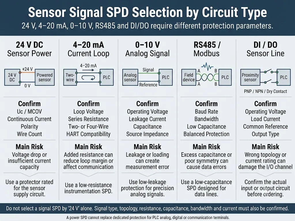
| Segnale | Uso tipico | Confermare prima | Rischio principale | Azione successiva |
|---|---|---|---|---|
| Alimentazione sensore 24V DC | Alimentazione per sensori di prossimità, trasmettitori o strumenti remoti | Uc / MCOV Attuale Polarità | L'SPD potrebbe creare troppa caduta di tensione o potrebbe non trasportare la corrente richiesta. | Confermare se il cavo trasporta solo alimentazione o combina conduttori di alimentazione e di segnale. [1][5] |
| 4-20mA o HART | Trasmettitori di pressione, portata, livello e di processo | Tensione di loop Resistenza HART | Una resistenza extra può utilizzare parte della tensione necessaria al trasmettitore. | Inviare l'alimentazione del loop, la scheda tecnica del trasmettitore e i dati dell'ingresso analogico. [5][6] |
| 0–10V AI o AO | Sensori analogici, attuatori e I/O analogici PLC | Dispersione Capacitanz Riferimento | La dispersione o il carico elettrico possono spostare il valore misurato. | Fornire il range del segnale, l'impedenza della sorgente e l'errore di misura accettabile. [5][6] |
| RS485 o Modbus | Reti PLC, BMS, telemetria e I/O remoto | Baud rate Capacitanz Numero di fili | Una capacità eccessiva può distorcere il segnale dati e causare errori di comunicazione. | Utilizzare la guida RS485 per il cablaggio A/B dettagliato, la schermatura e i controlli di terminazione. [1][4][6] |
| DI o DO | Interruttori di prossimità, contatti puliti, allarmi e uscite a transistor | PNP / NPN Corrente di carico Filo comune | Il circuito errato potrebbe collegare riferimenti condivisi o sovraccaricare il protettore. | Confermare il tipo di ingresso/uscita, la tensione, la corrente e il conduttore comune condiviso. [5] |
Installare l'SPD dove il cavo esposto entra nella zona protetta
Proteggere prima l'estremità dell'armadio. Aggiungere la protezione lato campo quando anche il dispositivo remoto o il percorso del cavo sono esposti. [2][3][7]
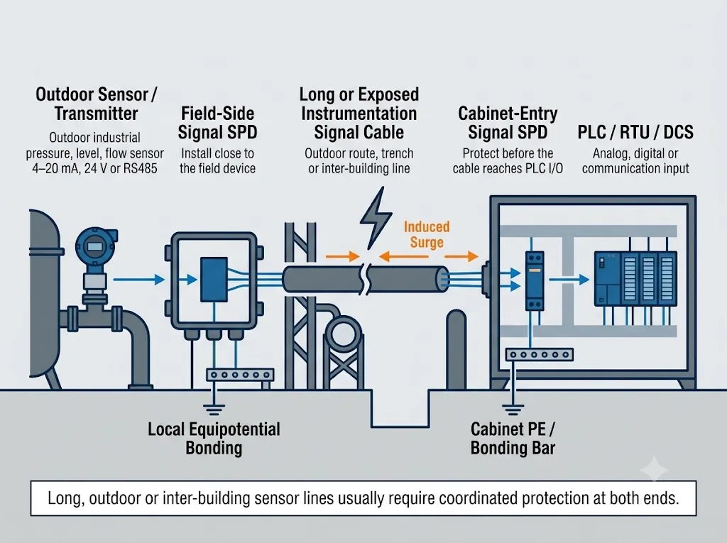
Protezione ingresso armadio
Installare l'SPD vicino all'ingresso del cavo o all'area di smistamento. Non far passare un lungo cavo di campo non protetto accanto al PLC. [2][7]
Protezione lato campo
Aggiungere la protezione vicino a un trasmettitore esterno, traliccio, serbatoio, pompa o scatola di giunzione remota quando il dispositivo di campo è esposto. [2][3]
Protezione su entrambe le estremità
Valutare entrambe le estremità quando il cavo attraversa edifici, aree esterne, zone di protezione contro i fulmini o zone di collegamento equipotenziale separate. [2][3][7]
Mantenere breve il collegamento di messa a terra dell'SPD. Un conduttore lungo aggiunge tensione induttiva durante una sovratensione. Ciò può aumentare la tensione rilevata dall'apparecchiatura protetta. [6][7]
Quattro parametri SPD che possono influenzare il normale funzionamento
Questi parametri spiegano perché un protettore non può essere selezionato in base alla sola tensione.
1. Resistenza di serie
Questa è la resistenza aggiuntiva introdotta dall'SPD nel circuito.
2. Corrente di dispersione
Si tratta di una piccola corrente che può fluire attraverso l'SPD durante il normale funzionamento.
3. Capacità e larghezza di banda
Questi parametri mostrano con quanta facilità un segnale dati variabile può passare attraverso il protettore.
4. Messa a terra e disposizione della schermatura
L'SPD necessita di un breve percorso di scarica verso il sistema equipotenziale locale.
Informazioni richieste prima della conferma di modello, campione o preventivo
Una richiesta che indica solo “SPD segnale 24 V” non è sufficiente per una selezione affidabile.
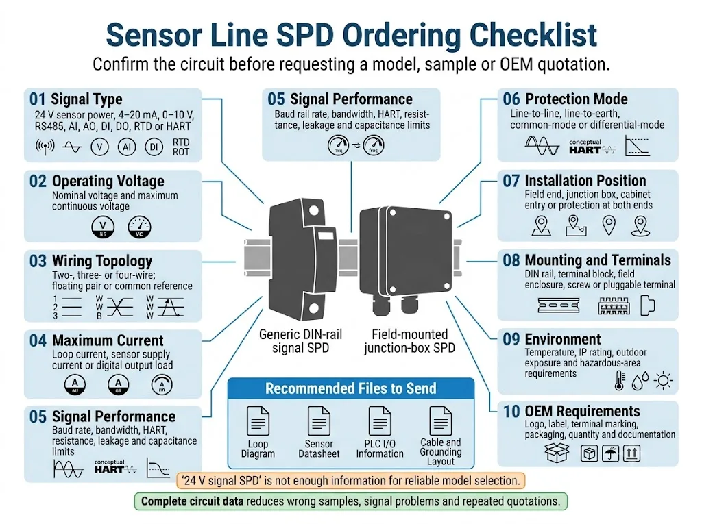
24 V, 4–20 mA, HART, 0–10 V, RS485, DI, DO o altro segnale.
Tensione nominale e massima tensione continua.
Circuito a due, tre o quattro fili e assegnazione dei conduttori.
Corrente di carico del loop, alimentazione sensore o uscita digitale.
Baud rate, HART, limiti di resistenza, dispersione o capacità.
Lunghezza, percorso, esposizione esterna e sezioni tra edifici.
Ingresso armadio, dispositivo di campo, scatola di derivazione o entrambe le estremità.
Punto di collegamento locale, terminazione della schermatura e metodo di riferimento.
Temperatura, grado IP, esigenze per aree esterne e pericolose.
Logo, etichetta, contrassegni terminali, quantità, imballaggio e documenti.
Chi specifica o acquista normalmente gli SPD per linee di sensori?
Produttori di quadri elettrici
Per la protezione di PLC, RTU, I/O analogici, I/O remoti e ingresso cavi di campo.
System integrator industriali
Per progetti di trattamento acque, automazione di fabbrica, BMS, telemetria e controllo di processo.
Acquirenti OEM e private-label
Per corrispondenza modelli, marcatura terminali, etichette personalizzate, imballaggio e forniture all'ingrosso.
Progetti idrici e di pompaggio
Per segnali esterni di livello, pressione, portata, interruttore a galleggiante e stazioni remote.
Team di manutenzione industriale
Per guasti ripetuti ai sensori, canali PLC instabili e linee di strumentazione esposte.
Distributori industriali
Per gamme di SPD di segnale a magazzino che devono coprire tensioni e tipi di segnale chiaramente definiti.
Inviare lo schema di loop, non solo "SPD per segnale 24V"
LEEYEE può esaminare il tipo di segnale, la tensione, il numero di fili, la corrente, il percorso dei cavi, il metodo di montaggio e i requisiti OEM prima della conferma del modello.
Domande sulla protezione contro le sovratensioni per linee di sensori
Ogni sensore esterno ha bisogno di un protettore contro le sovratensioni?
Non automaticamente. Verificare la lunghezza del cavo, l'esposizione all'esterno, le zone di protezione dai fulmini, il valore delle apparecchiature e la protezione esistente. L'esposizione all'esterno è un motivo valido per eseguire una valutazione del rischio di sovratensione. [2][3]
Devono essere installati SPD della linea del sensore a entrambe le estremità?
Valutare entrambe le estremità quando il cavo attraversa edifici, aree esterne o zone di collegamento locale separate. Un cavo interno corto all'interno di una struttura ben collegata potrebbe non richiedere la stessa configurazione. [2][3][7]
Può un SPD proteggere sia l'alimentazione a 24V che un segnale da 4 a 20 mA?
Solo quando è progettato esattamente per quel circuito combinato. Una coppia di alimentazione e una coppia di segnale analogico possono avere requisiti diversi in termini di corrente, resistenza, dispersione e modalità di protezione. [5][6]
Può un SPD del segnale influenzare la misurazione o la comunicazione?
Sì, se selezionato in modo errato. La resistenza in serie può influire su un loop di corrente. La dispersione può influire su una tensione analogica. Una capacità eccessiva può influire su un segnale dati. [5][6]
Quali informazioni sono richieste per la conferma del modello?
Fornire il tipo di segnale, la tensione, il numero di fili, la corrente, la velocità dei dati o il requisito HART, il percorso dei cavi, la posizione di installazione, la disposizione della messa a terra e l'ambiente. [1][2]
Fonti autorevoli utilizzate in questa guida
- [1] IEC 61643-21:2025 — Dispositivi di protezione contro le sovratensioni a bassa tensione collegati a reti di telecomunicazione e segnalazione: requisiti di prestazione e metodi di prova.
- [2] IEC 61643-22:2015 — Principi di selezione, funzionamento, ubicazione e coordinamento per SPD di reti di telecomunicazione e segnalazione.
- [3] IEC 62305-4:2024 — Protezione dei sistemi elettrici ed elettronici all'interno delle strutture contro gli effetti elettromagnetici dei fulmini.
- [4] Dispositivo di protezione contro le sovratensioni per segnali dati LEEYEE LY10 — Dati pubblicati su tensione, corrente, velocità di trasmissione, perdita di inserzione e installazione su guida DIN.
- [5] Phoenix Contact — Fondamenti per la protezione dalle sovratensioni — Circuiti di strumentazione e controllo, loop 4–20mA flottanti, segnali binari e misurazioni di resistenza.
- [6] Eaton MTL — Protezione contro fulmini e sovratensioni: principi di base — Funzionamento dell'SPD di segnale, impedenza in serie, dispersione, capacità ed effetti sui circuiti di segnale normali.
- [7] Eaton MTL — Guida alla messa a terra per la protezione dalle sovratensioni — Collegamenti equipotenziali, schermi dei cavi, collegamenti a terra locali e installazioni da campo a sala di controllo.
La selezione finale deve essere verificata rispetto alla scheda tecnica del sensore, del trasmettitore, del PLC o del controller, alla valutazione del rischio di fulminazione del progetto e ai dati tecnici dell'SPD selezionato.
