
Los sistemas de señalización ferroviaria conectan salas de enclavamiento, salas de relés, armarios de vía y equipos expuestos junto a la vía mediante largos cables de potencia, control y comunicación. Estas rutas conductoras pueden transportar sobretensiones inducidas por rayos, transitorios de conmutación y diferencias de potencial de tierra hacia interfaces de señalización sensibles. [9] [10]
Una protección eficaz contra sobretensiones en la señalización ferroviaria no se logra seleccionando el SPD con la mayor clasificación en kA. El dispositivo debe limitar la tensión transitoria sin alterar la señal normal, sin crear una vía inaceptable a tierra ni introducir un modo de fallo que entre en conflicto con el sistema de seguridad ferroviario. [7] [10]
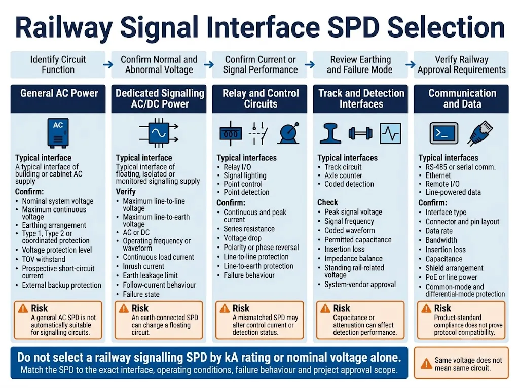
Seleccione un SPD para señalización ferroviaria según la interfaz exacta a proteger, no solo por la tensión nominal o la clasificación de corriente de impulso. Confirme la función del circuito, la tensión máxima continua, la corriente de servicio, la forma de onda o velocidad de datos, la caída de tensión permitida, el esquema de puesta a tierra, la fuga aceptable, los modos de protección y el comportamiento ante fallos antes de elegir un modelo. [4] [9] [10]
- Revise por separado los cables de potencia, señal, control y comunicación.
- Coloque la protección en los límites definidos de entrada de cables y de los equipos.
- Compruebe tanto el funcionamiento normal como las condiciones previsibles de fallo del SPD.
- No conecte a tierra un circuito flotante o supervisado por aislamiento sin una revisión aprobada del sistema.
- Confirme los requisitos de aprobación del operador, del proveedor del sistema y del proyecto antes de realizar el pedido.
Índice
Por qué la señalización ferroviaria requiere protección contra sobretensiones específica para cada interfaz
Una instalación de señalización ferroviaria puede contener alimentación ordinaria de edificio, alimentación dedicada para señalización, circuitos de relé, circuitos de vía, circuitos de accionamiento de agujas, interfaces de contadores de ejes, datos serie y Ethernet.
Estos circuitos no comparten la misma tensión, corriente, frecuencia, impedancia ni función de seguridad. Un dispositivo adecuado para una entrada general de armario de 230 V AC puede no ser apropiado para una alimentación de señalización flotante o un circuito de detección de baja energía. [9] [10]
La IEC 62236-4 especifica los requisitos de emisión electromagnética e inmunidad para aparatos de señalización ferroviaria y telecomunicaciones. La IEC 62425 aborda el ciclo de vida de seguridad funcional de los sistemas electrónicos de señalización relacionados con la seguridad. [6] [7]
Estas normas ayudan a definir el entorno ferroviario y el proceso de seguridad del sistema. No hacen que un SPD industrial no revisado sea automáticamente apto para una interfaz de señalización ferroviaria.
Funcionamiento normal
El SPD no debe introducir una caída de tensión, capacitancia, pérdida de inserción, fuga o desequilibrio de impedancia excesivos.
Condición de fallo
El proyecto debe considerar si un SPD envejecido o averiado podría cortocircuitar conductores o conectar un circuito supervisado a tierra.
Entorno junto a la vía
La temperatura, la humedad, la vibración, la contaminación y las condiciones del envolvente deben corresponderse con la ubicación real de la instalación.
Aprobación del proyecto
El cumplimiento de la norma del producto no sustituye la aprobación del operador, la aceptación del proveedor del sistema ni la validación del proyecto.
¿Por dónde pueden entrar las sobretensiones en un sistema de señalización ferroviaria?
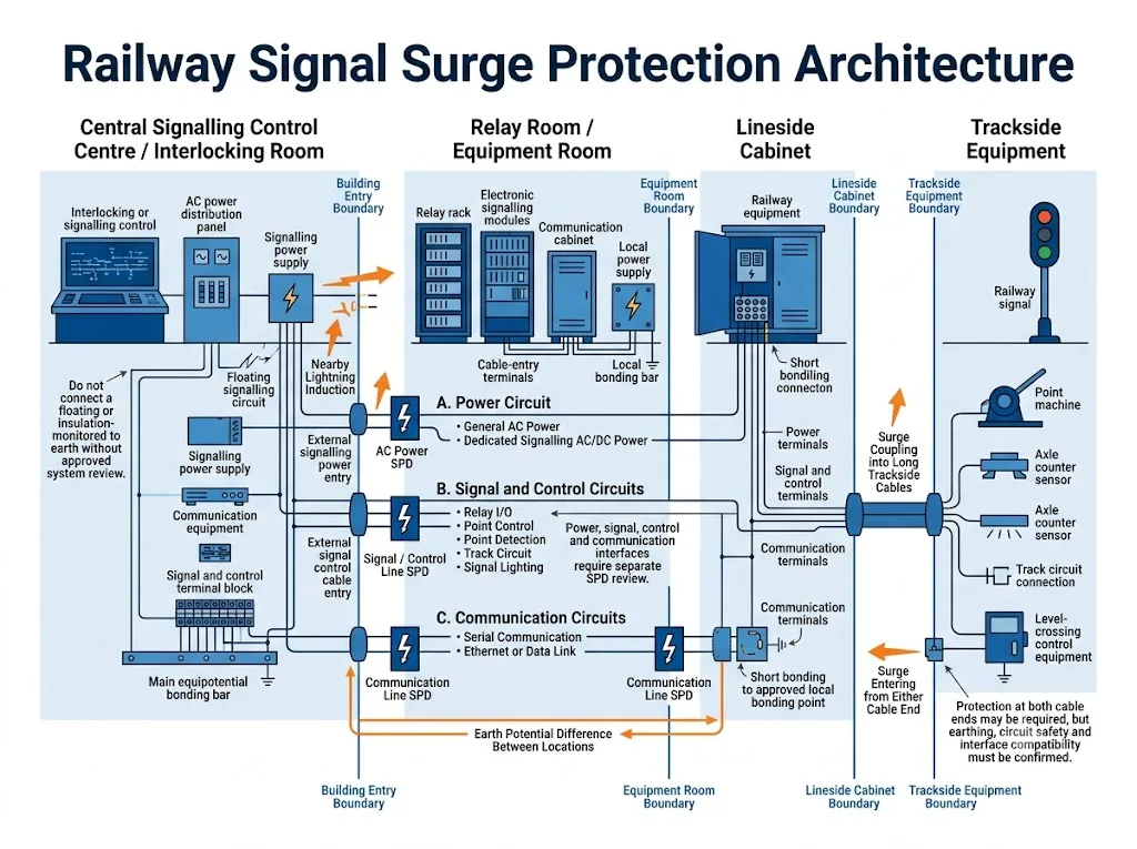
El equipo de señalización ferroviaria está distribuido a lo largo de grandes distancias. Los cables conductores pueden salir de un edificio protegido, seguir un recorrido expuesto junto a la vía y terminar en equipos de campo con un potencial de tierra local diferente. [9]
Por tanto, una sobretensión transitoria puede entrar por varias rutas y desde cualquiera de los extremos de un cable. Todo conductor metálico que entre o salga de una ubicación de equipos debe incluirse en la revisión del riesgo de sobretensiones del proyecto.
| Ruta de entrada de sobretensiones | Fuente típica. | Qué debe revisarse |
|---|---|---|
| Alimentación de CA entrante | Acoplamiento por rayo, conmutación de la red o una falla eléctrica aguas arriba | Tipo de suministro, disposición de puesta a tierra, exposición a TOV, condiciones de cortocircuito y capacidad de soportar del equipo |
| Cable largo junto a la vía | Acoplamiento inductivo o capacitivo por rayos cercanos | Longitud del cable, trazado, blindaje, equipos protegidos en ambos extremos y unión local |
| Conectado a la vía férrea o circuito de detección | Potencial de la vía, perturbación relacionada con la tracción o fallas cercanas | Tensión sostenida, forma de onda de la señal, aislamiento, referencia a tierra y modo de protección aprobado |
| Cobre de comunicaciones | Cable de datos externo, gabinete remoto o conexión de mástil | Tasa de datos, ancho de banda, pérdida de inserción, capacitancia, conexión de blindaje y alimentación por línea |
| Línea de control e indicación | Conductores largos conectados a señales, máquinas de aguja, cruces y detectores | Corriente continua, corriente de irrupción, resistencia en serie, caída de tensión y estado de falla |
| Diferencia de potencial de tierra | Corriente de rayo o una falla de alta tensión a tierra | Condiciones locales de EPR, trayectos de tierra remota y el diseño aprobado de enlace equipotencial |
Conclusión de adquisición: un SPD de alimentación en CA no protege las interfaces externas de señalización, control y comunicaciones. Cada trayecto conductor requiere una revisión de compatibilidad independiente.
¿Cómo debe escalonarse la protección en todo el sistema ferroviario?
La protección contra sobretensiones de la señalización ferroviaria debe seguir la ruta física del cable y los límites entre la sala de equipos central, el gabinete intermedio y el equipo de campo.
La primera etapa de protección reduce la energía de sobretensión en el límite de la instalación. Puede requerirse protección adicional más cerca del equipo sensible cuando la longitud del cable, la inmunidad del equipo o la tensión restante exijan otra etapa coordinada. [4] [9]
Sala de equipos central o ubicación del enclavamiento
Revise la alimentación entrante de la instalación, la alimentación dedicada de señalización, los servicios externos de comunicaciones y todos los circuitos de señalización de cobre que salen de la sala.
La protección de límite debe instalarse cerca de la entrada de cable correspondiente. Los conductores largos entre el punto de entrada, el SPD y el equipo protegido pueden aumentar la tensión efectiva durante un transitorio rápido. [4]
Sala de relés o gabinete intermedio
Un gabinete intermedio puede recibir un transitorio desde cualquiera de los lados de un cable externo largo. La protección debe colocarse en el límite definido de entrada del cable, en lugar de profundamente dentro del gabinete después de un tramo largo de conductor sin protección.
Para un SPD de dos puertos, confirme la orientación de línea y equipo, la capacidad de corriente de carga, la resistencia en serie, la disposición de bornes y el efecto de retirar el módulo de protección.
Gabinete junto a la vía y equipo junto a la vía
Las señales, los accionamientos de agujas, los contadores de ejes, los circuitos de vía y los equipos de paso a nivel pueden conectarse mediante tendidos de cables largos y expuestos.
La protección en el extremo de la sala de equipos puede no limitar suficientemente un transitorio que aparezca cerca del extremo remoto. Puede ser necesario revisar ambos límites del cable, pero la disposición final depende del aislamiento del circuito, la puesta a tierra, el diseño del equipo y los requisitos del operador. [4] [9]
Añadir protección línea-tierra a un circuito flotante o con supervisión de aislamiento puede crear una nueva vía de fuga o de fallo. Los modos de protección permitidos y la conexión a tierra deben confirmarse en el diseño del sistema aprobado.
La protección del circuito de potencia comienza por identificar la alimentación
La primera decisión es si el circuito es alimentación general de servicios o alimentación dedicada de señalización ferroviaria. Su tensión, puesta a tierra, corriente de fallo y requisitos de aprobación pueden ser diferentes.
Alimentación de CA de baja tensión general
La norma IEC 61643-01:2024 contiene requisitos comunes para los SPD, mientras que la IEC 61643-11:2025 se aplica a los SPD conectados a sistemas de alimentación de CA de baja tensión. [1] [2]
La selección sigue dependiendo de la tensión real de alimentación, la disposición de puesta a tierra, la exposición a sobretensiones temporales, la corriente de cortocircuito prospectiva, la protección externa de respaldo y el nivel de protección de tensión requerido.
Una disposición de SPD de CA de Tipo 1, Tipo 2 o coordinada puede ser pertinente para la alimentación del edificio o para la entrada general de un gabinete. No debe extenderse automáticamente a un circuito de seguridad de señalización.
Alimentación dedicada de CA para señalización
La alimentación de señalización ferroviaria puede utilizar una disposición aislada o IT. Puede emplearse la supervisión de fugas a tierra para detectar la primera conexión entre un conductor activo y tierra. [9] [10]
En esta situación, el proveedor necesita la tensión máxima entre conductores y desde cada conductor a tierra. También deben revisarse la fuga normal del SPD y su comportamiento previsible en caso de fallo.
Alimentación dedicada de CC para señalización
Para un circuito de alimentación de CC de señalización, confirme la tensión máxima continua, la tensión de fallo, la corriente continua, la corriente de entrada, la corriente de fallo disponible y las características de la fuente de alimentación.
La norma IEC 61643-41:2025 se aplica a los SPD conectados a circuitos de alimentación de CC de hasta 1.500 V CC y se utiliza junto con la IEC 61643-01. La norma señala que se requiere una consideración cuidadosa cuando la fuente no presenta la característica lineal tensión-corriente asumida por sus ensayos. Puede ser pertinente para aplicaciones ferroviarias cuando no exista una norma de producto más específica, pero su aplicabilidad debe confirmarse para el circuito concreto. [1] [5]
La IEC 61643-41 se aplica a circuitos de alimentación de CC. No debe tratarse como la norma general de producto para una interfaz de señalización, detección o comunicación codificada.
Cuando la tecnología de protección seleccionada puede conducir corriente de seguimiento, la corriente de fallo de CC disponible y el método de desconexión requerido deben revisarse antes de la aprobación. [1] [5]
Una tensión de servicio innecesariamente alta puede dejar una tensión residual mayor en el equipo protegido. Una tensión de servicio demasiado baja puede exponer el SPD a un esfuerzo de sobretensión continua o temporal.
Los circuitos de señal, vía y control deben revisarse por separado
“Línea de señalización ferroviaria” no es una única interfaz eléctrica. Los circuitos de vía, las salidas de iluminación de señales, los bucles de relés, los accionamientos de máquinas de agujas y las interfaces de contadores de ejes pueden operar con diferentes tensiones, corrientes, frecuencias y formas de onda. [9] [10]
| Tipo de circuito | Características importantes | Riesgos de compatibilidad de DPS |
|---|---|---|
| Circuito de vía | Funcionamiento en CC, CA de baja frecuencia, audiofrecuencia o codificado | Tensión de limitación, capacitancia, atenuación y tensión de reposo relacionada con el carril |
| Iluminación de señales | Salida de CA o CC, controlador electrónico, cable de campo largo y posible corriente de arranque | Corriente de carga, tensión residual, esfuerzo de modo común y puesta a tierra en el extremo del equipo |
| Accionamiento de máquina de agujas | Corriente del motor o actuador, inversión de polaridad o fase y conductores largos | Capacidad de corriente, caída de tensión, compatibilidad de inversión y corriente de seguimiento |
| Detección de puntos | Retroalimentación relacionada con la seguridad, detección por relé o codificada | Fuga a tierra, fallo por cortocircuito y umbrales de detección alterados |
| Interfaz de contador de ejes | Interfaz de sensor, alimentación y datos específica del fabricante | Ancho de banda, impedancia, disposición de pines y aprobación del proveedor del sistema |
| Entrada o salida de relé | Corriente de bobina, estado del contacto, resistencia de bucle y cableado de campo externo | Resistencia en serie, caída de tensión y fallo revelado seguro |
Significado para el comprador: no se debe aprobar un “SPD ferroviario de 24 V” para todas las interfaces de 24 V. La tensión nominal no describe la señal, la carga, la conexión a tierra ni la función de seguridad.
La protección de las líneas de comunicación debe preservar el rendimiento de los datos
Los sistemas de monitorización y control ferroviario pueden utilizar interfaces serie, Ethernet, líneas de telecomunicaciones de cobre, E/S remotas o sistemas de transmisión específicos del fabricante.
La norma IEC 61643-21:2025 se aplica a los SPD conectados a redes de telecomunicaciones y señalización, incluidas las redes que transportan alimentación y datos en los mismos conductores. La norma IEC 61643-22:2015 proporciona principios de selección, funcionamiento, ubicación y coordinación para estos dispositivos. [3] [4]
El cumplimiento de las normas de producto es una prueba útil. No demuestra la compatibilidad con todos los protocolos ferroviarios, conectores, disposiciones de cables o sistemas de comunicación relacionados con la seguridad.
Confirme estos parámetros de comunicación
- Interfaz física, conector y disposición de los terminales.
- Número de conductores y conexión del blindaje del cable.
- Tensión nominal y máxima de la línea.
- Velocidad de transmisión de datos y ancho de banda requerido.
- Pérdida de inserción permitida y desequilibrio de impedancia.
- Capacitancia máxima y resistencia en serie.
- Potencia transportada por la línea, incluyendo PoE u otra función alimentada por línea.
- Requisitos de protección en modo común y modo diferencial.
- Conexión permitida al chasis, a la red de equipotencialidad o a tierra.
La transmisión por fibra óptica elimina una ruta de datos conductora, pero la fuente de alimentación, el convertidor, el armario, la pantalla o el elemento de refuerzo metálico asociados pueden seguir requiriendo una evaluación de sobretensiones y equipotencialidad.
¿Qué parámetros del SPD deben coincidir con la interfaz ferroviaria?
La columna más importante es "Por qué es importante". Muestra por qué un valor de la hoja de datos puede cambiar el rendimiento de la protección, el funcionamiento normal o la aprobación del proyecto.
| Parámetro SPD | Qué confirmar | Por qué es importante |
|---|---|---|
| Uc o tensión máxima de operación continua | Tensión permanente máxima entre líneas y entre línea y tierra | Evita el estrés continuo y la conducción no deseada |
| Tensión limitadora medida o Up | Resistencia al impulso del equipo y margen de coordinación requerido | Un alto valor nominal de corriente no es útil si la tensión residual es demasiado alta |
| Categoría de ensayo de sobretensión y forma de onda | Método de ensayo requerido, nivel de corriente, nivel de tensión y modo de protección | Los valores nominales obtenidos con diferentes formas de onda no pueden compararse solo por kA |
| Corriente de carga continua y de pico | Corriente normal, irrupción, corriente inversa y corriente de funcionamiento de corta duración | Evita el sobrecalentamiento, la caída de tensión excesiva y la interrupción del circuito |
| Resistencia en serie | Resistencia de bucle máxima permitida y pérdida en el conductor | Importante para cables largos, bucles de relés y cargas de baja tensión |
| Ancho de banda y pérdida de inserción | Frecuencia de señal real, forma de onda codificada o velocidad de datos | Evita la distorsión o la pérdida de señales de detección y comunicación |
| Capacitancia y equilibrio de impedancia | Límites de interfaz y características de los cables | Puede afectar a los umbrales de detección y a la transmisión de alta frecuencia |
| Resistencia de aislamiento y fugas | Corriente permitida a tierra y umbrales de supervisión de aislamiento | Evita una ruta no intencionada u oculta a tierra |
| Modos de protección | Línea a línea, línea a tierra o una combinación coordinada | Una referencia a tierra incorrecta puede cambiar el comportamiento del circuito |
| Comportamiento ante fallos | Circuito abierto, cortocircuito, fallo a tierra, desconexión e indicación de estado | El SPD averiado no debe crear un estado inaceptable en el sistema |
| Clasificación ambiental | Temperatura, humedad, vibración, contaminación, envolvente y posición de montaje | Las condiciones de la vía y de la sala de equipos pueden diferir sustancialmente |
| Interfaz mecánica | Tamaño del terminal, montaje, huella, módulo reemplazable y marcado | La coincidencia de parámetros eléctricos no garantiza la compatibilidad de la instalación |
Conclusión para la adquisición: solicite la ficha técnica completa, el circuito de protección, los datos de transmisión, la información sobre fallos, las instrucciones de instalación y el alcance exacto del informe de pruebas antes de aprobar un SPD ferroviario.
Por qué el modo de fallo del SPD importa en la señalización ferroviaria
Muchos circuitos de señalización ferroviaria dependen del mantenimiento del aislamiento eléctrico entre conductores, entre circuitos separados y entre un circuito y tierra.
Un SPD añade componentes entre estos puntos. Si un componente de protección falla con baja resistencia, puede crear una conexión que no existía en el circuito original. [7] [10]
¿Qué es un fallo a tierra no revelado?
Un fallo a tierra no revelado es una conexión a tierra que existe sin producir un fallo visible o detectado de forma inmediata.
Un segundo fallo en otro conductor puede crear una trayectoria de corriente no deseada a través de tierra. En un sistema de señalización relacionado con la seguridad, esta posibilidad debe incluirse en la evaluación de seguridad del sistema en lugar de asumir que es inofensiva. [7] [9] [10]
La revisión técnica debe determinar:
- Si un componente de protección interno puede fallar con baja resistencia.
- Si dicho fallo es de línea a línea o de línea a tierra.
- Si el fallo será revelado por una alarma, fusible, desconectador o monitor de fugas.
- Si el circuito pasa al estado seguro definido por el proyecto.
- Si la retirada del módulo de protección cambia o interrumpe el circuito de señalización.
- Si la indicación de fin de vida útil es independiente del estado normal de la señal.
La puesta a tierra y la unión equipotencial determinan el rendimiento real de la protección
Un SPD no hace que la corriente de sobretensión desaparezca. Desvía la corriente a través de una trayectoria definida. Por lo tanto, el SPD, el equipo protegido, el armario, la pantalla del cable y el sistema de conexión equipotencial deben estar dispuestos de forma que las diferencias de tensión peligrosas se limiten durante el transitorio. [4] [9]
Mantenga las trayectorias de la corriente de sobretensión cortas y directas
La corriente de sobretensión rápida produce tensión a través de la inductancia del conductor. Las conexiones largas del SPD pueden aumentar la tensión que aparece en el equipo protegido, incluso cuando la ficha técnica del SPD muestra un nivel de protección bajo. [4]
Instale el SPD cerca de la entrada de cables pertinente o de la interfaz protegida. Evite bucles innecesarios y mantenga los conductores sin protección separados del cableado interno protegido.
Utilice el concepto de conexión equipotencial ferroviario aprobado.
La barra de puesta a tierra general más cercana no es automáticamente el punto de conexión correcto.
Las instalaciones ferroviarias pueden tener restricciones relacionadas con la corriente de retorno de tracción, fallos a tierra de alta tensión, elevación del potencial de tierra, corrientes erráticas, sistemas de tierra separados y monitorización del aislamiento de la señalización. [9] [10]
La norma Transport for NSW TS 05258:2.0, por ejemplo, incluye requisitos específicos del operador sobre resistencia a la elevación del potencial de tierra, corriente residual a tierra, fuentes de alimentación IT de señalización y modos de fallo del SPD. Estos requisitos pertenecen a dicho operador y no deben copiarse ciegamente en otro proyecto ferroviario. [10]
Durante un transitorio rápido, la diferencia de tensión local puede estar dominada por la impedancia de los conductores y de la conexión equipotencial. La disposición física y la conexión equipotencial siguen siendo fundamentales.
¿Qué normas se aplican y qué demuestran?
La protección contra sobretensiones ferroviaria puede implicar normas de producto SPD, normas ferroviarias de compatibilidad electromagnética (EMC), normas medioambientales, normas de seguridad funcional y especificaciones específicas del operador.
Estos documentos cumplen funciones diferentes. Un certificado no debe presentarse como prueba de todos los requisitos de un proyecto. La edición aplicable y la versión nacional adoptada deben confirmarse para cada proyecto.
| Norma o requisito | Lo que respalda | Lo que no demuestra por sí solo |
|---|---|---|
| IEC 61643-01:2024 | Requisitos, pruebas y clasificaciones comunes para SPD de baja tensión | Compatibilidad con una interfaz de señalización ferroviaria específica |
| IEC 61643-11:2025 | Requisitos y pruebas para SPD conectados a sistemas de alimentación de baja tensión de CA | Idoneidad para un circuito de señalización ferroviaria relacionado con la seguridad |
| IEC 61643-21:2025 | Requisitos y pruebas para SPD de redes de telecomunicaciones y señalización | Compatibilidad con un protocolo ferroviario o plataforma de señalización específica |
| IEC 61643-22:2015 | Principios de selección, funcionamiento, ubicación y coordinación para SPD de redes de señalización | Aprobación del operador o aceptación del proveedor del sistema |
| IEC 61643-41:2025 | Requisitos y pruebas para SPD conectados a circuitos de alimentación de CC pertinentes | Idoneidad para una señal codificada, detector o circuito de comunicación |
| IEC 62236-4:2018 | Requisitos de emisión e inmunidad de compatibilidad electromagnética (CEM) para aparatos de señalización y telecomunicaciones ferroviarias | Capacidad de sobretensión del SPD o comportamiento de fallo seguro de la interfaz |
| IEC 62425:2025 | Ciclo de vida de seguridad funcional para sistemas electrónicos de señalización relacionados con la seguridad | Rendimiento eléctrico de un modelo de SPD particular |
| IEC 62498-3:2010 | Condiciones ambientales para equipos de señalización y telecomunicaciones | Idoneidad para el armario, la envolvente o la ubicación exactos |
| AS 7708:2017 | Requisitos de puesta a tierra y protección contra sobretensiones para señalización ferroviaria australiana durante el ciclo de vida del activo | Aceptación por una autoridad ferroviaria fuera de su ámbito de aplicación |
| Especificación del operador o del proyecto | Configuraciones aprobadas, pruebas adicionales, requisitos de instalación y mantenimiento | Aprobación para otra autoridad ferroviaria o plataforma de señalización |
| Aceptación del proveedor del sistema | Compatibilidad con una interfaz de señalización y una versión de equipo definidas | Compatibilidad universal con todos los productos y configuraciones de cableado |
Nota para el comprador: verifique el número de modelo exacto, la configuración del circuito, la edición del informe y el alcance de la aprobación. Es posible que un certificado para una familia de productos no cubra todos los voltajes, disposiciones de terminales o aplicaciones ferroviarias.
Por qué es importante la norma AS 7708
La norma AS 7708:2017 se titula específicamente Puesta a tierra y protección contra sobretensiones en señalización y sigue estando listada como vigente por la Australian Rail Industry Standards Organisation. Su alcance abarca el diseño, la construcción, las pruebas, la puesta en servicio, la monitorización, el mantenimiento, la modificación y el desmantelamiento de la puesta a tierra y la protección contra sobretensiones en la señalización ferroviaria. [9]
Esto hace que la norma AS 7708 sea más relevante para la puesta a tierra y protección contra sobretensiones en señalización ferroviaria que una norma general para dispositivos de protección contra sobretensiones (SPD). Sin embargo, sigue siendo una norma ferroviaria australiana y no sustituye los requisitos de otros países, operadores o sistemas de señalización.
Un ejemplo actual específico de un operador
La norma Transport for NSW TS 05258:2.0 se publicó y entró en vigor el 23 de junio de 2025. Identifica las normas AS/RISSB 7708, IEC 61643-11 e IEC 61643-21 entre las normas aplicables para equipos de protección contra sobretensiones. [10]
La especificación distingue entre SPD de alimentación de 230 V CA de uso general, SPD de interfaz de comunicación y SPD utilizados en la alimentación de señalización o puertos de entrada y salida de equipos. También establece que cualquier SPD utilizado como parte del sistema de seguridad de señalización requiere una homologación de tipo conforme al proceso TfNSW aplicable. [10]
Esto es una prueba útil de lo detallados que pueden ser los requisitos de un operador ferroviario. No es una especificación universal para todos los países o sistemas ferroviarios.
Errores comunes en la selección de SPD ferroviarios
| Suposición incorrecta | Por qué es arriesgado | Mejor confirmación |
|---|---|---|
| El mayor valor nominal en kA es el mejor SPD. | La tensión residual, las fugas y el rendimiento de la señal pueden seguir siendo inadecuados. | Compare Uc, Up, la forma de onda, los modos de protección y los límites de la interfaz. |
| Todos los circuitos con el mismo voltaje nominal utilizan el mismo SPD. | La corriente, la frecuencia, la impedancia, la puesta a tierra y la función de seguridad pueden diferir. | Identifique la función exacta del circuito y la forma de onda de operación. |
| Conectar cada conductor a tierra proporciona una protección más fuerte. | Puede crear fugas o una ruta de fallo insegura en un circuito flotante. | Utilice únicamente los modos de protección aprobados entre líneas y entre línea y tierra. |
| La protección en la sala de control protege el dispositivo de campo remoto. | Un cable externo largo puede recibir un transitorio cerca del extremo de campo. | Revise tanto los límites del cable como la disposición de la conexión equipotencial local. |
| Un certificado IEC no equivale a una aprobación ferroviaria. | La compatibilidad del sistema, la seguridad funcional y los requisitos del operador permanecen sin verificar. | Verifique la homologación, los documentos del proyecto y la aceptación por parte del proveedor del sistema. |
| Un SPD mecánicamente similar es un reemplazo directo. | Los circuitos internos, los modos de fallo, los niveles de protección y los informes pueden diferir. | Complete una comparación de parámetros, validación de muestras y revisión formal de cambios. |
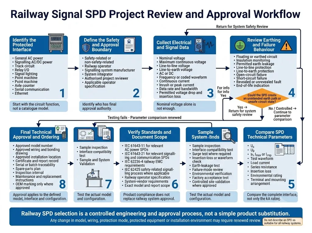
Flujo de revisión de un proyecto de SPD para señalización ferroviaria
Una consulta sobre un SPD ferroviario debe comenzar por la interfaz protegida y los requisitos de aprobación, no por un número de modelo de catálogo.
-
Identifique la función protegida.
Indique si el circuito es de alimentación general, alimentación de señalización, circuito de vía, iluminación de señales, control de desvíos, detección de desvíos, contador de ejes, E/S de relé, comunicación serie o Ethernet. -
Defina el límite de seguridad y aprobación.
Confirme si el circuito realiza o admite una función relacionada con la seguridad. Identifique al operador ferroviario, al fabricante de señalización, al integrador del sistema y al revisor autorizado. -
Recopile los datos eléctricos completos.
Proporcione tensión nominal y máxima, CA o CC, frecuencia o forma de onda, corriente continua, corriente de irrupción, corriente de cortocircuito disponible y caída de tensión aceptable. -
Recopile los datos de transmisión.
Para interfaces de señalización y comunicación, proporcione el ancho de banda, la velocidad de datos, la impedancia, los límites de capacitancia y la pérdida de inserción permitida. -
Revise la puesta a tierra y el comportamiento ante fallos.
Confirme los circuitos flotantes, el monitoreo de fugas a tierra, los modos de protección aprobados y el estado del circuito requerido tras un fallo del SPD. -
Revise la instalación física.
Proporcione la longitud del cable, el trazado del cable, la disposición del blindaje, el entorno del armario, los requisitos de terminales, el método de montaje y el plano de conexión equipotencial. -
Verifique los estándares y el alcance del documento.
Compare los informes de productos, las especificaciones ferroviarias, el alcance del modelo, la evidencia ambiental, las instrucciones de instalación y los requisitos de mantenimiento. -
Complete la validación de la muestra y del sistema.
Realice las pruebas de laboratorio, de aceptación en fábrica, de interfaz o en sitio controlado requeridas por el proyecto antes de la aprobación final del modelo.
¿Qué debe confirmarse antes de hacer el pedido?
Lista de control para la consulta de SPD de señalización ferroviaria
- País y autoridad ferroviaria
- Proyecto y plataforma de señalización
- Equipo protegido
- Función exacta de la interfaz
- Clasificación relacionada con la seguridad
- Voltaje nominal
- Voltaje máximo continuo
- Tensión máxima línea a tierra
- CA, CC y frecuencia
- Forma de onda de la señal o velocidad de datos
- Corriente de carga continua
- Corriente de irrupción o de corta duración
- Corriente de falla disponible
- Caída de tensión permitida
- Capacitancia permitida
- Pérdida de inserción permitida
- Circuito flotante o a tierra
- Monitorización de fugas a tierra
- Modos de protección requeridos
- Pruebas de sobretensión requeridas
- Longitud y ruta del cable
- Disposición de blindaje y conexión equipotencial
- Entorno interior o de vía
- Límites de temperatura y vibración
- Normas aplicables
- Requisitos de homologación de tipo
- Informes y certificados requeridos
- Requisitos de terminales y montaje
- Requisito de estado o alarma remota
- Cantidad y módulos de repuesto
- Marcado y documentación OEM
Comparta los datos de interfaz antes de solicitar un modelo de SPD ferroviario
LEEYEE puede respaldar una revisión preliminar de los parámetros basada en la información de la interfaz y los documentos del proyecto que usted proporcione. La revisión puede ayudar a identificar si una familia de productos de protección contra sobretensiones existente puede ser relevante, si se requiere adaptación o pruebas adicionales, o si la aplicación queda fuera del alcance actual del producto.
Esta revisión preliminar no constituye una homologación ferroviaria. La idoneidad y aceptación finales recaen exclusivamente en el operador ferroviario, el fabricante del sistema de señalización, el integrador de sistemas y el revisor de proyectos autorizado.
LEEYEE es un proveedor especializado en protección contra sobretensiones y protección de baja tensión. CNSPD es la plataforma de LEEYEE centrada en la protección contra sobretensiones para compradores técnicos globales. Diseñado para proteger. Confiable a largo plazo.
Preguntas frecuentes
¿Se puede utilizar un SPD de señal industrial estándar para señalización ferroviaria?
No sin una revisión de la interfaz y del proyecto. Un dispositivo puede cumplir con una norma general de SPD pero, aun así, ser incompatible con la tensión, la forma de onda, el límite de fuga, el estado de fallo, el entorno o los requisitos de homologación del circuito ferroviario.
¿La protección contra sobretensiones para señales ferroviarias se selecciona principalmente por su capacidad en kA?
No. La capacidad de corriente de sobretensión es solo un parámetro. Uc, Up, el modo de protección, la corriente de carga, la resistencia en serie, la capacitancia, la pérdida de inserción, la fuga a tierra y el comportamiento ante fallos pueden ser más importantes para una interfaz en particular.
¿Cada cable largo de vía requiere un SPD en ambos extremos?
Los cables externos largos a menudo requieren que se revisen ambos límites, ya que un transitorio puede ingresar cerca de cualquiera de las ubicaciones. La disposición final depende del aislamiento del circuito, la puesta a tierra, el equipo protegido y los requisitos del operador ferroviario.
¿Puede un SPD afectar a un circuito de vía o a una interfaz de contador de ejes?
Sí. La resistencia serie, la capacitancia, la pérdida por inserción, las fugas y el comportamiento de limitación pueden afectar a la detección o a la comunicación. La compatibilidad debe comprobarse a la frecuencia, tensión y corriente reales de funcionamiento.
¿Qué norma se aplica a un SPD para líneas de comunicación ferroviaria?
La norma IEC 61643-21:2025 es una norma de producto pertinente para los SPD conectados a redes de telecomunicaciones y señalización. El proyecto también puede requerir la norma IEC 61643-22, normas ferroviarias de compatibilidad electromagnética (CEM), especificaciones del operador, homologación de tipo y aceptación por parte del proveedor del sistema.
¿Puede utilizarse la norma IEC 61643-41 para todos los circuitos ferroviarios de CC?
No. La norma IEC 61643-41:2025 se aplica a circuitos de potencia de CC pertinentes. No se aplica automáticamente a las interfaces de señalización codificada, detección o comunicación. Debe confirmarse la función real del circuito y cualquier requisito de producto específico para el ferrocarril.
¿Es suficiente el cumplimiento de la norma IEC 61643-21 para la homologación ferroviaria?
No. Proporciona pruebas conforme a la norma de producto. Por sí sola, no confirma la compatibilidad con un circuito de señalización, función de seguridad, requisito del operador o configuración de instalación en particular.
¿Por qué es importante la corriente de fuga a tierra en la señalización ferroviaria?
Algunos circuitos de señalización son flotantes o tienen monitorización de aislamiento. Un SPD conectado a tierra puede añadir fugas durante el funcionamiento normal o tras un fallo. Debe confirmarse el valor permitido y el método de supervisión para el proyecto.
¿Se puede sustituir un SPD homologado para ferrocarriles por un modelo similar?
No automáticamente. La alternativa puede diferir en cuanto al circuito eléctrico, el comportamiento ante fallos, los terminales, las dimensiones, el nivel de protección y el alcance del informe de ensayo. Puede requerirse una comparación formal, la validación de muestras y una homologación.
¿Qué información es más importante al solicitar un presupuesto de un SPD ferroviario?
Envíe la interfaz exacta, la tensión máxima de funcionamiento, la corriente, la forma de onda o la velocidad de datos, la disposición de la puesta a tierra, la fuga permitida, el trazado del cable, los ensayos requeridos y la autoridad ferroviaria que realiza la homologación.
¿Se puede decir que un SPD es adecuado para todos los sistemas ferroviarios?
Ningún proveedor responsable debería hacer tal afirmación. La idoneidad se aplica normalmente a un modelo definido, una interfaz protegida, una plataforma de señalización, una configuración de instalación y un alcance de homologación.
Lectura técnica relacionada
Estas páginas explican los principios generales de la protección contra sobretensiones. Los requisitos del operador específicos del sector ferroviario, la compatibilidad de las interfaces y la homologación de seguridad deben seguir confirmándose por separado.
Referencias
- Comisión Electrotécnica Internacional, IEC 61643-01:2024, Dispositivos de protección contra sobretensiones de baja tensión – Parte 01: Requisitos generales y métodos de ensayo. Página de publicación oficial de la IEC.
- Comisión Electrotécnica Internacional, IEC 61643-11:2025, Dispositivos de protección contra sobretensiones de baja tensión – Parte 11: Dispositivos de protección contra sobretensiones conectados a sistemas de alimentación de baja tensión de CA – Requisitos y métodos de ensayo. Página de publicación oficial de la IEC.
- Comisión Electrotécnica Internacional, IEC 61643-21:2025, Dispositivos de protección contra sobretensiones de baja tensión – Parte 21: Dispositivos de protección contra sobretensiones conectados a redes de telecomunicaciones y señalización – Requisitos y métodos de ensayo. Página de publicación oficial de la IEC.
- Comisión Electrotécnica Internacional, IEC 61643-22:2015, Dispositivos de protección contra sobretensiones de baja tensión – Parte 22: Dispositivos de protección contra sobretensiones conectados a redes de telecomunicaciones y señalización – Principios de selección y aplicación. Página de publicación oficial de la IEC.
- Comisión Electrotécnica Internacional, IEC 61643-41:2025, Dispositivos de protección contra sobretensiones de baja tensión – Parte 41: Dispositivos de protección contra sobretensiones conectados a sistemas de alimentación de baja tensión de CC – Requisitos y métodos de ensayo. Página de publicación oficial de la IEC.
- Comisión Electrotécnica Internacional, IEC 62236-4:2018, Aplicaciones ferroviarias – Compatibilidad electromagnética – Parte 4: Emisión e inmunidad de los aparatos de señalización y telecomunicación. Página de publicación oficial de la IEC.
- Comisión Electrotécnica Internacional, IEC 62425:2025, Aplicaciones ferroviarias – Sistemas de comunicación, señalización y procesamiento – Sistemas electrónicos relacionados con la seguridad para la señalización. Página de publicación oficial de la IEC.
- Comisión Electrotécnica Internacional, IEC 62498-3:2010, Aplicaciones ferroviarias: condiciones ambientales para el equipo. Parte 3: Equipos de señalización y telecomunicaciones. Página de publicación oficial de la IEC.
- Australian Rail Industry Standards Organisation, AS 7708:2017, Puesta a tierra y protección contra sobretensiones en señalización. ARISO clasifica esta norma como vigente. Página oficial de la norma ARISO.
- Transport for NSW, TS 05258:2.0, Requisitos comunes para equipos de sistemas de control y señalización, fecha de emisión y entrada en vigor: 23 de junio de 2025. PDF oficial de Transport for NSW.
