
Un protector contra sobretensiones PoE no se selecciona solo por el conector RJ45. Para un proyecto de CCTV o red al aire libre, el protector debe coincidir con la posición de instalación, tasa de datos Ethernet, tipo de PoE, pares alimentados, voltaje de operación, método de conexión a tierra y envoltura ambiental.
Las cámaras PoE exteriores normalmente requieren protección contra sobretensiones cuando el cable Ethernet sale de un edificio, corre a lo largo de un techo, se conecta a un poste, cruza un área expuesta o vincula equipos con diferentes condiciones de puesta a tierra.
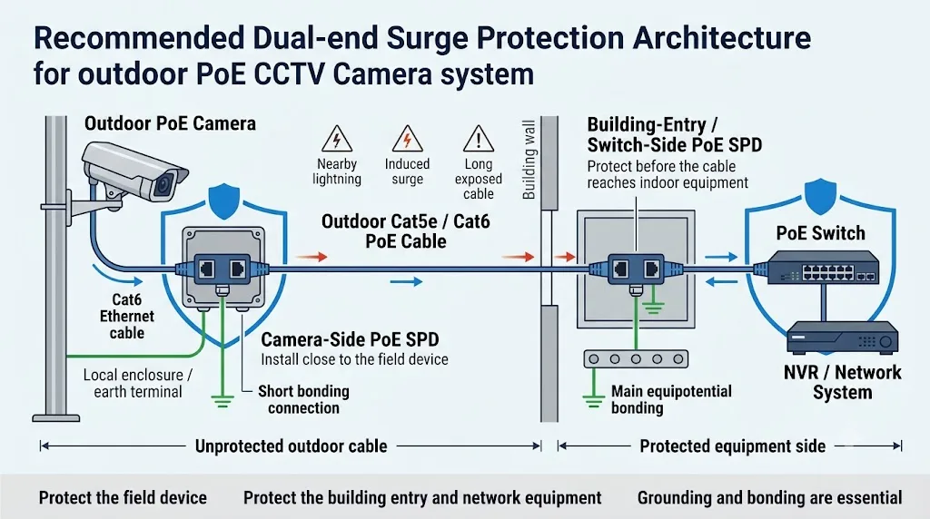
Para un cable de cámara corto montado en la pared exterior del mismo edificio, la protección en la entrada del edificio o en el lado del equipo de red puede ser suficiente después de una evaluación de riesgo del sitio. Para un poste remoto, cámara en el techo, cámara en el estacionamiento o carrera exterior larga, un arreglo de ingeniería común es instalar un SPD PoE cerca del dispositivo de campo y otro cerca de la entrada del edificio, conmutador PoE o inyector.
Limita la energía de sobretensión antes de que llegue a la cámara exterior, punto de acceso inalámbrico u otro dispositivo de campo.
Ayuda a proteger el conmutador PoE, inyector, NVR y la red interior más amplia.
Comúnmente considerado para enlaces de cobre exteriores largos, expuestos o remotos donde ambos dispositivos conectados requieren protección.
Índice
¿Necesita cada cámara PoE un protector contra sobretensiones?
No. Se debe seleccionar un SPD PoE según la ruta del cable, nivel de exposición, disposición a tierra, valor del equipo protegido y tiempo de inactividad aceptable.
Un cable corto interior entre equipos en la misma habitación protegida no tiene la misma exposición que un largo cable de cobre que va desde un edificio de control hasta una cámara en un poste de acero.
El riesgo aumenta cuando un cable Ethernet conductor se extiende fuera del edificio o conecta equipos instalados en diferentes ubicaciones físicas.
¿Dónde debe instalarse un protector contra sobretensiones PoE?
Instale el protector lo más cerca posible del equipo o del límite de protección que se pretende proteger. Mantenga la sección del cable entre el SPD y el puerto protegido corta.
No dirija el cable protegido directamente junto al cable de entrada expuesto durante una larga distancia. La separación física ayuda a reducir la energía de sobretensión que puede acoplarse nuevamente al lado protegido.
Cerca de la cámara
Protege el dispositivo de campo de la energía de sobretensión que entra a través del cable Ethernet exterior. La conexión protegida del SPD a la cámara debe mantenerse corta.
En la entrada del edificio
Controla la energía de sobretensión antes de que el cable de cobre exterior continúe hacia una sala de red interior, cabinet o otra zona protegida.
Antes del interruptor o inyector
Protege el conmutador PoE, el inyector, el NVR y la infraestructura de red conectada cuando el punto de entrada y la posición del equipo están cerca uno del otro.
Protege el límite, no solo el conector.
La posición correcta se determina por dónde entra el cable expuesto en una zona protegida y qué dispositivo debe ser protegido. Un SPD colgado al lado de un conmutador sin la ruta de unión especificada no es un diseño de protección completo.
¿Lado de la cámara, lado del conmutador o en ambos extremos?
“Siempre usa dos” y “un SPD es suficiente” son ambas respuestas simplificadas en exceso. Usa la exposición, la ruta del cable y los límites de protección para tomar la decisión.
| Condición del proyecto | Enfoque de protección típico | Controles de ingeniería importantes |
|---|---|---|
| Cable corto interior en una sala protegida |
Evaluación de riesgos
Un SPD PoE dedicado puede no ser siempre necesario. |
Verifica la protección de energía entrante, el valor del equipo y los requisitos locales. |
| Cámara montada en la pared exterior del mismo edificio |
Revisión del lado de entrada
Considera la protección donde el cable entra al edificio o cerca del equipo de red protegido. |
Exposición del cable, protección contra rayos en la fachada, longitud del cable y unión de la cámara. |
| Cámara en un poste remoto o en un mástil de estacionamiento |
Uso común de doble extremo
Uno cerca de la cámara y uno en la entrada del edificio o en el lado del conmutador. |
Uniendo el poste, recinto exterior, ruta del cable, camino de conexión a tierra y separación de los cables de alimentación. |
| Cableado largo en azotea, perímetro o área abierta | Uso común de doble extremo | Apantallamiento de cables, zonas de rayos, exposición a sobretensiones inducidas y coordinación de SPD. |
| Enlace Ethernet de cobre entre edificios separados | Proteger ambos límites | Evaluar la unión equipotencial y diferentes potenciales de tierra. Considerar si la fibra es la mejor solución del sistema. |
| Cámara PTZ de alto valor o sistema de seguridad crítico | Protección coordinada | Proteger la línea de comunicación y confirmar la protección coordinada de potencia AC o DC para el sistema completo. |
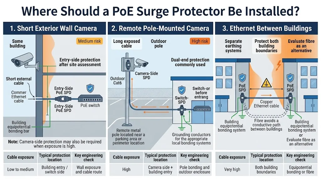
Dos SPD no solucionan todos los riesgos interedificados
Donde el Ethernet de cobre conecta estructuras separadas, el diseñador también debe evaluar los sistemas de puesta a tierra y la unión equipotencial. La fibra debe ser evaluada al eliminar la conexión conductora cuando sea técnica y comercialmente viable.
¿Todos los protectores contra sobretensiones RJ45 soportan PoE?
No. RJ45 describe la conexión física, no el rendimiento eléctrico y de transmisión completo del protector.
Dos productos pueden tener ambos conectores RJ45 pero soportar diferentes tasas de datos, voltajes de funcionamiento, pares alimentados, niveles de potencia PoE, categorías de cable y métodos de conexión a tierra.
10/100 Mbps, 1 Gigabit, 2.5 Gigabit, 5 Gigabit o 10 Gigabit.
IEEE 802.3af, 802.3at, 802.3bt Tipo 3 o 802.3bt Tipo 4.
Verifique el funcionamiento de dos pares y cuatro pares y confirme cuáles conductores están protegidos.
Cat5e, Cat6, Cat6A, UTP, FTP u otra construcción apantallada.
Un error común de adquisición
Un protector PoE de 100 Mbps puede alimentar la cámara con éxito, pero convertirse en un cuello de botella cuando el proyecto requiere transmisión Gigabit. Una etiqueta de Gigabit tampoco prueba automáticamente la compatibilidad con cada nivel de potencia PoE++.
La disponibilidad depende del modelo seleccionado. No asuma que cada LEEYEE o SPD RJ45 de terceros soporta cada tasa de datos o tipo de PoE listado en esta guía.
¿El SPD PoE soporta Alternativa A, Alternativa B y PoE de cuatro pares?
Esta pregunta es especialmente importante cuando un proyecto utiliza equipos de 10/100 Mbps, Gigabit Ethernet o dispositivos IEEE 802.3bt de alta potencia.
La Alternativa A y la Alternativa B también se describen comúnmente como Modo A y Modo B. El comprador debe confirmar la asignación real de pines y los conductores protegidos en lugar de confiar solo en el nombre de marketing.
| Disposición de PoE | Cómo se transporta la energía | Lo que debe confirmar el comprador de SPD |
|---|---|---|
|
Alternativa A
A menudo llamado Modo A |
La energía se aplica a través de los pares que también transportan datos de Ethernet en enlaces de 10/100 Mbps. | Confirme la protección de los conductores de datos y energía requeridos, voltaje de operación, polaridad y corriente continua. |
|
Alternativa B
A menudo llamado Modo B |
En enlaces de 10/100 Mbps, la energía se puede aplicar a través de los pares que no se utilizan para la transmisión de datos. | Confirme que los pares de repuesto requeridos están protegidos y que el producto admite la asignación real de pines del proyecto. |
| Ethernet Gigabit | Los cuatro pares participan en la transmisión de datos. | Confirme la protección completa de la señal de ocho conductores, el ancho de banda del canal, la pérdida de inserción y el rendimiento de pérdida de retorno. |
|
PoE de cuatro pares
IEEE 802.3bt |
La energía se entrega a través de ambos conjuntos de pares, mientras que los cuatro pares también pueden transportar datos. | Confirme la protección de todos los pares, la capacidad de corriente continua, la caída de voltaje, el aumento de temperatura y el tipo de PoE admitido. |
“Todos los pares protegidos” deben estar respaldados por evidencia
Solicite el diagrama de conductores del modelo exacto, la especificación de transmisión y el informe de prueba. Un dibujo genérico de RJ45 de ocho pines no prueba que cada conductor tenga el circuito de protección correcto o la capacidad de energía-corriente.
El estándar IEEE PoE no es lo mismo que el PoE pasivo.
El equipo estándar IEEE PoE utiliza procedimientos de detección, clasificación y entrega de potencia definidos. PoE pasivo puede aplicar voltaje directamente a los pines RJ45 seleccionados sin el mismo proceso de negociación.
Algunos equipos inalámbricos para exteriores, puentes, puntos de acceso y sistemas de CCTV propietarios utilizan 24V pasivo, 48V pasivo u otro arreglo específico de un proveedor.
El hecho de que ambos sistemas utilicen un conector RJ45 no hace que sus protectores contra sobretensiones sean intercambiables.
| Sistema | Información del comprador requerida | Riesgo principal cuando se selecciona incorrectamente |
|---|---|---|
| IEEE 802.3af / at / bt | Tipo de PoE, clase de potencia, salida de PSE, demanda de PD, categoría de cable y velocidad de red. | Capacidad de corriente insuficiente, protección de pares incorrecta, caída de voltaje excesiva o rendimiento de datos reducido. |
| PoE Pasivo | Voltaje exacto, polaridad, asignación de pines, pares alimentados, corriente máxima y modelo del dispositivo. | Voltaje de sujeción incorrecto, suposiciones de polaridad erróneas o un camino de corriente incompatible. |
| Sistema de alta potencia propietario | Diagrama de cableado del fabricante, demanda de inicio, voltaje de funcionamiento, corriente pico y tasa de transmisión requerida. | Sobrecalentamiento, caída de voltaje, fallo de inicio o daño al equipo conectado. |
Los compradores de estándares PoE deben confirmar.
La velocidad de red y la potencia PoE son especificaciones separadas. Confirme ambas. Un protector debe soportar la potencia DC requerida sin caída de voltaje excesiva o aumento de temperatura, manteniendo el rendimiento requerido de la señal Ethernet.
| Tipo de PoE | Referencia IEEE | Salida máxima de PSE | Potencia aproximada disponible en PD | Confirmación del comprador para el SPD |
|---|---|---|---|---|
| Tipo 1 / PoE | IEEE 802.3af | 15.4 W | Alrededor de 13 W | Tensión de trabajo, disposición de alimentación, tasa de datos y conductores protegidos. |
| Tipo 2 / PoE+ | IEEE 802.3at | 30 W | 25.5 W | Corriente continua, temperatura del conector, caída de tensión y longitud de cable soportada. |
| Tipo 3 / PoE++ | IEEE 802.3bt | Hasta 60 W | Hasta aproximadamente 51 W | Compatibilidad de cuatro pares, corriente por camino y rendimiento de señal de todos los pares. |
| Tipo 4 / PoE de alta potencia | IEEE 802.3bt | Hasta 90 W | Hasta aproximadamente 71 W | Confirme que el modelo exacto de SPD está clasificado y probado para la aplicación de cuatro pares de alta potencia requerida. |
Estas cifras de potencia describen la categoría del sistema PoE. No prueban que un modelo de SPD particular sea compatible. La aprobación final debe basarse en la hoja de datos del protector solicitado y en la evidencia de prueba.
¿Necesita un protector contra sobretensiones PoE una conexión a tierra?
El protector necesita el camino de descarga y conexión especificado por su fabricante. Sin ese camino, el SPD puede no desviar la energía de sobretensión como se pretende.
No todos los productos utilizan la misma construcción. Algunos SPDs PoE proporcionan un terminal de tierra dedicado. Otros productos están diseñados para conectarse a través de un gabinete metálico conectado a tierra, riel DIN, sistema de conector apantallado u otro método de montaje definido por el fabricante.
Un cable apantallado no es automáticamente una solución SPD completa
La apantallamiento puede ser una parte importante del sistema, pero su función depende de la cámara, PSE, conectores, paneles de parcheo y disposición de puesta a tierra. Siga el diseño aprobado para el enlace completo en lugar de tratar el apantallamiento del cable como un reemplazo universal para un protector externo.
¿Se puede instalar un SPD RJ45 interior junto a una cámara exterior?
Solo cuando esté instalado dentro de un recinto adecuado y el ensamblaje completo cumpla con las condiciones ambientales del sitio.
La clasificación IP del protector RJ45, los pasacables, los sellos de los conectores, el drenaje, el control de condensación y la temperatura de funcionamiento deben ser considerados.
Armario interior
Las unidades internas de riel DIN o compactas pueden ser adecuadas cuando se instalan dentro de un armario de red protegido con la puesta a tierra requerida.
Caja de conexión exterior
Confirme la clasificación IP del recinto, el sellado del pasacables, el montaje interno, el riesgo de condensación y el espacio para el conductor de puesta a tierra.
Montaje directo al aire libre
Utilice un producto específicamente diseñado y aprobado para instalación directa en pared, poste o en exteriores expuestos.
| Elemento ambiental | Lo que el comprador debe confirmar |
|---|---|
| Protección contra la entrada | Clasificación del recinto SPD o la clasificación de la caja de conexión externa completa. |
| Temperatura | Temperatura mínima y máxima de funcionamiento en el poste real, techo o ubicación al borde de la carretera. |
| Humedad y condensación | Prevención de condensación interna, drenaje y entrada de cable sellada. |
| Corrosión | Alojamiento, terminales, tornillos y materiales de montaje para ubicaciones costeras, industriales o de alta humedad. |
| Montaje mecánico | Instalación en riel DIN, pared, panel, poste, caja de conexión o rack. |
| Gestión de cables | Radio de curvatura, alivio de tensión, terminación de blindaje y separación de cables protegidos y no protegidos. |
¿Qué evidencia se debe verificar para el modelo exacto de SPD PoE?
Esta guía explica cómo seleccionar una categoría de producto. No es un sustituto de la hoja de datos, las instrucciones de instalación y la evidencia de prueba del modelo exacto que se está pidiendo.
No transfiera especificaciones de un modelo RJ45 a otro
Un SPD Ethernet no PoE, un SPD PoE de 100 Mbps, un SPD PoE de Gigabit y un SPD PoE++ de cuatro pares pueden utilizar carcasas RJ45 que parecen similares mientras tienen circuitos y límites de operación muy diferentes.
Hoja de datos del modelo exacto
Verifique el número de modelo, el voltaje de operación, la corriente continua, el tipo de PoE soportado, la velocidad de la red, la categoría de cable, el método de montaje y la clasificación ambiental.
Datos de prueba de sobretensión
Confirme la forma de onda de prueba, el modo de prueba, la corriente por conductor o par, los valores de protección de voltaje y la edición estándar aplicable.
Rendimiento de transmisión
Revise la tasa de Ethernet soportada, la pérdida de inserción, la pérdida de retorno y otros datos de rendimiento del canal requeridos por el proyecto.
Prueba de caída de corriente y voltaje PoE
Los proyectos de alta potencia deben confirmar la corriente continua, el aumento de temperatura y la caída de voltaje en la carga PoE prevista.
Diagrama de pares protegidos
Confirme qué conductores están protegidos y si el modelo admite Alternativa A, Alternativa B, Gigabit y alimentación de cuatro pares según sea necesario.
Dibujo de conexión a tierra e instalación
Verifique la dirección de LINE y EQUIPMENT, el terminal de unión, la conexión del recinto y la disposición máxima recomendada de los conductores.
Lo que LEEYEE debe confirmar antes de la cotización
LEEYEE debe adaptar la aplicación del comprador a un modelo disponible real y proporcionar la hoja de datos aplicable y los documentos de respaldo. No se debe asumir ninguna velocidad, tipo de PoE, norma de prueba o clasificación de sobretensión hasta que se confirme el modelo exacto.
Lista de verificación para la adquisición de protectores contra sobretensiones PoE.
No emita una orden utilizando solo “protector contra sobretensiones PoE RJ45” como la descripción. El proveedor necesita suficiente información para confirmar el rendimiento tanto de transmisión como de protección contra sobretensiones.
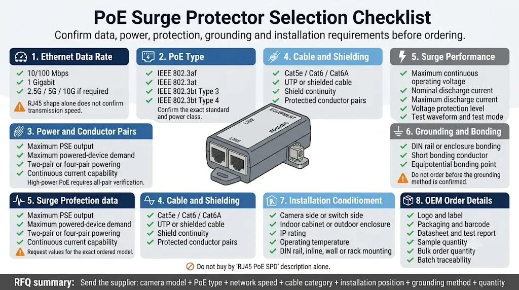
Cámara IP fija, cámara PTZ, punto de acceso inalámbrico, intercomunicador, control de acceso u otro equipo PoE.
Proporcione el modelo exacto de la cámara, punto de acceso, conmutador o inyector siempre que sea posible.
IEEE 802.3af, 802.3at, 802.3bt Tipo 3, 802.3bt Tipo 4 o un sistema pasivo propietario.
Potencia requerida en el PSE y en el dispositivo conectado, incluida la puesta en marcha, calefacción, iluminación IR y demanda del motor PTZ.
100 Mbps, 1 Gbps, 2.5 Gbps, 5 Gbps o 10 Gbps.
Cat5e, Cat6, Cat6A o el sistema de cableado estructurado especificado en el proyecto.
Cable UTP o apantallado, conectores RJ45 apantallados y continuidad de apantallamiento requerida.
Alternativa A, Alternativa B, dos pares, cuatro pares o una asignación de pines pasivos específica del proveedor.
Confirme la protección de todos los conductores de señal y potencia requeridos, particularmente para PoE Gigabit y de cuatro pares.
El voltaje de operación continua máximo debe ser compatible con el sistema PoE sin operación no deseada.
Onda de prueba, corriente por ruta, valores de protección de voltaje, rendimiento línea a línea y línea a tierra donde sea aplicable.
Ancho de banda soportado, pérdida por inserción, pérdida de retorno y método de prueba para la categoría de cable requerida y velocidad Ethernet.
Solicitar la edición estándar exacta e informe aplicable al modelo pedido, no solo una declaración genérica del catálogo.
Terminal dedicado, riel DIN, conexión a pantalla, caja metálica u otro método de unión definido por el fabricante.
Lado de la cámara, entrada del edificio, lado del conmutador, lado del inyector, armario o rack multicanal.
Instalación interior, caja de conexión externa o instalación directa al aire libre, incluyendo requisitos de IP y temperatura.
RJ45 en línea, riel DIN, montaje en pared, montaje en panel, montaje en poste, caja de pared multicanal o rack de 19 pulgadas.
Logo, etiqueta, color de carcasa, hoja de datos, embalaje, código de barras, inspección y trazabilidad de lote.
Cantidad de muestra, cantidad de proyecto, demanda anual, unidades de reemplazo y cronograma de entrega esperado.
Hoja de datos, plano de cableado, informe de prueba, registro de inspección, declaración y especificación de embalaje.
¿Qué se debe comprobar después de la instalación?
Un SPD PoE no debe ser aceptado solo porque la cámara se enciende. El instalador debe verificar la potencia, la comunicación, el sellado y la unión.
Errores comunes en la protección contra sobretensiones PoE.
RJ45 no confirma la potencia PoE, la tasa de datos, los pares protegidos o el rendimiento contra sobretensiones.
Un protector de línea de datos puede usar el mismo conector pero carecer del camino de voltaje y corriente requerido para PoE.
Un protector no puede funcionar como se espera cuando su camino de descarga falta o está instalado incorrectamente.
La cámara puede operar, pero la velocidad de la red y el rendimiento de video pueden estar restringidos.
Confirme el Tipo 3 o Tipo 4, potencia de cuatro pares, corriente máxima y los datos de prueba exactos del modelo pedido.
Los sistemas pasivos pueden usar diferentes voltajes, polaridades y asignaciones de pines a pesar de que el conector sea RJ45.
La humedad, la condensación y la corrosión de los conectores pueden causar fallos incluso cuando el circuito de sobretensión está correctamente seleccionado.
La protección eficaz de CCTV debe considerar tanto la línea Ethernet como la alimentación de CA o CC que alimenta el equipo de red.
Información a enviar antes de solicitar una cotización.
Proporcionar estos detalles ayuda al proveedor a evitar ofrecer un protector que se ajusta al conector pero no se adapta al proyecto.
Modelo de cámara o dispositivo:
Modelo de interruptor o inyector:
PoE estándar o PoE pasivo:
Estándar PoE: 802.3af / at / bt Tipo 3 / bt Tipo 4
Voltaje y polaridad de PoE pasivo, si corresponde:
Potencia máxima de la cámara o dispositivo:
Velocidad de red: 100M / 1G / 2.5G / 5G / 10G
Cable: Cat5e / Cat6 / Cat6A
Apantallado o no apantallado:
Alternativa A / Alternativa B / cuatro pares:
Longitud del cable:
Instalación: lado de la cámara / lado del interruptor / en ambos extremos
Montaje: en línea / riel DIN / pared / rack / caja exterior
Clasificación ambiental:
Parámetros requeridos para la prueba de sobretensión:
Método de puesta a tierra o conexión a tierra:
Cantidad:
Requisitos de logotipo OEM o embalaje:
Certificados y informes de prueba requeridos:
Preguntas frecuentes sobre protectores contra sobretensiones PoE.
¿Las cámaras PoE para exteriores necesitan protectores contra sobretensiones?
Deben ser evaluadas para protección contra sobretensiones cuando sus cables Ethernet de cobre corren al aire libre, salen de un edificio, se conectan a un poste, cruzan un área expuesta o conectan equipos en estructuras separadas. La disposición final depende de la exposición, la puesta a tierra, la ruta del cable y el tiempo de inactividad aceptable.
¿Debería instalarse el protector contra sobretensiones cerca de la cámara o del interruptor?
Instale el protector cerca del equipo o límite de protección que se pretende proteger. Las instalaciones remotas y muy expuestas comúnmente utilizan uno cerca del dispositivo de campo y otro en la entrada del edificio o el lado del equipo de red.
¿Se requiere un protector contra sobretensiones en ambos extremos de un cable Ethernet?
No para todos los cables. La protección de doble extremo se considera comúnmente para polos remotos, techos, tramos exteriores largos, cámaras críticas y enlaces entre estructuras separadas. Los enlaces cortos interiores pueden requerir un enfoque diferente.
¿Un protector contra sobretensiones PoE reducirá la velocidad de la red?
Un producto seleccionado correctamente debería soportar su velocidad de red declarada, pero un protector de menor categoría puede convertirse en un cuello de botella. Confirme la tasa de datos requerida y revise la información de pérdida de inserción y pruebas de transmisión donde esté disponible.
¿Cada SPD de Ethernet Gigabit soporta PoE++?
No. Gigabit describe el rendimiento de transmisión de datos. La compatibilidad con PoE++ también requiere el voltaje de operación adecuado, corriente continua, disposición de pares alimentados y rendimiento térmico.
¿Cuál es la diferencia entre PoE de Modo A y Modo B?
El Modo A y el Modo B son nombres comúnmente utilizados para la Alternativa A y la Alternativa B. Describen diferentes disposiciones de pares de conductores para entregar energía. El SPD debe proteger los pares y la asignación de pines reales utilizados por el proyecto.
¿Un protector contra sobretensiones PoE++ necesita proteger todos los ocho conductores?
Los sistemas IEEE 802.3bt de cuatro pares usan todos los cuatro pares para energía y pueden usar todos los cuatro pares para datos. Por lo tanto, el protector seleccionado debería tener documentada la compatibilidad con todos los pares y un rendimiento de corriente y transmisión suficiente.
¿Se puede usar un SPD estándar de PoE para PoE pasivo?
No automáticamente. PoE pasivo puede usar un voltaje diferente, polaridad o asignación de pines. Confirme el modelo exacto de equipo y el cableado de PoE pasivo antes de seleccionar el SPD.
¿Se puede usar un protector contra sobretensiones de Ethernet normal para PoE?
Solo cuando el fabricante confirma la compatibilidad con el voltaje de PoE requerido, pares alimentados, corriente, clase de potencia y velocidad de red. Un SPD de Ethernet solo para datos puede no ser adecuado.
¿Un SPD de PoE necesita un cable a tierra separado?
Depende del diseño del producto. Algunos modelos usan un terminal de tierra dedicado, mientras que otros se conectan a través de un conector apantallado, una carcasa aterrizada, riel DIN o un punto de montaje metálico. Siga las instrucciones de instalación exactas para el modelo seleccionado.
¿Se puede instalar un SPD de PoE interior en una caja exterior?
Puede ser posible cuando la carcasa completa proporciona la protección requerida contra la entrada, la temperatura, la condensación y la corrosión. Las bocinas de cable y la disposición de puesta a tierra también deben incluirse en la evaluación.
¿Qué norma se aplica a los protectores contra sobretensiones para líneas de PoE?
La IEC 61643-21 cubre los SPD conectados a redes de telecomunicaciones y señalización, incluidas las redes que pueden proporcionar energía en la misma línea, como PoE. Los compradores deben solicitar evidencia aplicable al modelo de producto exacto y edición de norma.
Fuentes y lecturas adicionales.
- IEC, IEC 61643-21:2025 — Dispositivos de protección contra sobretensiones conectados a redes de telecomunicaciones y señalización. Ver publicación de IEC
- IEC, IEC 61643-22:2015 — Principios de selección y aplicación para SPDs conectados a redes de telecomunicaciones y señalización. Ver publicación de IEC
- IEEE Standards Association, IEEE 802.3bt-2018 — Energía a través de Ethernet sobre cuatro pares. Ver resumen de estándares de IEEE
- Fluke Networks, Energía a través de Ethernet de cuatro pares y niveles de energía de PoE. Ver resumen técnico
- Axis Communications, Documento Técnico sobre Picos de Energía — cámara exterior, ejemplos de protección de entrada de edificios y protección de doble punto. Ver documento técnico de Axis
- DEHN, Protección contra Sobretensiones para Sistemas de CCTV — disposiciones de protección para cámaras IP y cables LAN. Ver documento técnico de DEHN
- Ubiquiti, Ficha Técnica del Protector contra Sobretensiones de Ethernet — ejemplo de instalación en campo y en entrada de edificios. Ver ficha técnica de Ubiquiti
Se proporcionan fuentes externas para referencia técnica general. La selección de productos debe basarse en las condiciones reales del proyecto, los requisitos locales aplicables y la ficha técnica y evidencia de prueba de el modelo SPD solicitado.
Continuar la revisión técnica.
¿Necesita un SPD PoE confirmado para su proyecto de CCTV?
Enviar el modelo de la cámara o dispositivo, tipo de PoE, tasa de datos, categoría de cable, disposición del par alimentado, posición de instalación, método de conexión a tierra y cantidad requerida. LEEYEE confirmará si un modelo disponible coincide con el proyecto antes de realizar un pedido de muestra o a granel.
