
Índice
Cómo seleccionar un protector contra sobretensiones de señal de 24V
Una marca de 24V por sí sola no es suficiente para seleccionar un protector contra sobretensiones para un circuito de sensor o E/S de PLC. El SPD correcto también debe coincidir con el tipo de señal, topología del circuito, cantidad de conductores, corriente de lazo, resistencia en serie permisible, nivel de protección y posición de instalación.
Utilice un SPD de línea de señal, no un SPD de potencia general de 24V CC, cuando un sensor externo, transmisor, interruptor o actuador esté conectado a un canal I/O de PLC. Seleccione el SPD de acuerdo a la función DI, DO, AI o AO. Para circuitos analógicos, confirme la resistencia en serie, la corriente de fuga, la capacitancia y el margen de voltaje del lazo antes de aprobar el modelo.
Circuitos de sensor y I/O de PLC de 24V, incluyendo conmutación digital, 4–20mA, 0–10V, disposición de conductores, instalación en campo y protección de entrada de gabinete.
Buses de potencia de 24V CC generales, potencia de telecomunicaciones de 48V, circuitos DC de energía solar FV o cableado de protocolo RS485. Esas aplicaciones requieren reglas de selección separadas.
Guía rápida de selección de SPD de señal de 24V
Comience con el circuito real. No seleccione solo de la tensión nominal.
Configuración de bucle flotante o de referencia, tensión máxima del bucle, corriente del bucle, baja resistencia en serie, baja fuga y compatibilidad HART donde sea necesario.
Se requiere confirmación del modelo+24V, 0V, salida de conmutación, lógica de fuente o de drenaje, umbral de entrada , corriente de fuga y disposición de terminales.
Revisión del cableado requeridaTipo de salida, corriente de carga, polaridad, conductor común y máximo corriente de operación continua.
Revisión de carga requeridaMáximo voltaje de señal, topología de referencia, corriente de fuga, resistencia en serie, capacitancia y error de señal permisible.
Se requiere confirmación del modeloInterfaz, voltaje de operación, conteo de conductores, velocidad en baudios, capacitancia, disposición de aterrizaje y apantallamiento.
Dirección del producto LY10Voltaje de energía DC, corriente máxima de carga, polaridad, condiciones de falla y requisitos de SPD del circuito de energía.
Selección de SPD de energía separadaIndique el circuito como “dos cables 4–20mA AI,” “tres cables PNP DI,” “24V transistor DO” o “0–10V AO.” Una solicitud que dice solo “24V SPD” no contiene suficiente información para una selección de modelo confiable.
¿Cuándo necesita un sensor de 24V o una línea de E/S de PLC un SPD?
No todos los cables de control internos necesitan protección individual. La decisión depende de la exposición del cable, límites de instalación, sensibilidad del equipo y el costo operativo de la falla.
Dispositivo de Campo Exterior
Los sensores y transmisores instalados al aire libre pueden recibir voltaje transitorio inducido a través de su cableado de campo incluso sin una caída directa de rayos.
Ruta de Cable Largo
Los cables largos proporcionan una mayor ruta de acoplamiento para los efectos de rayos, transitorios de conmutación y diferencias de voltaje entre ubicaciones.
Conexión entre Edificios
El cableado entre edificios, cajas de unión al aire libre o diferentes zonas equipotenciales puede exponer ambos extremos del circuito.
Alto Costo de Inactividad
Las plantas de proceso, sistemas de agua, estaciones de bombeo y líneas de producción automatizadas pueden justificar la protección local porque una tarjeta de E/S fallida puede detener un sistema más grande.
El circuito puede operar a solo 24V, pero un transitorio acoplado en el cable puede superar la capacidad de soporte de la entrada del PLC, el transmisor o la interfaz del sensor. Las pruebas de inmunidad a sobretensiones y el rendimiento de SPD de señal se evalúan por separado del voltaje de operación normal. [1][3]
SPD de potencia de 24V CC vs SPD de señal de 24V
Ambos productos pueden incluir “24V” en su descripción, pero protegen circuitos diferentes y no pueden ser seleccionados por los mismos parámetros.
| Punto de selección. | SPD de Potencia de 24V CC | SPD de Señal de 24V |
|---|---|---|
| Propósito principal | Proteger una fuente de alimentación de CC, un bus de potencia auxiliar o la entrada de un equipo alimentado. | Proteger E/S de PLC, sensor, transmisor o conductores de control de bajo voltaje. |
| Corriente normal | Puede que necesite llevar la corriente continua de una carga completa. | Normalmente lleva una corriente de señal o de lazo más baja y debe preservar el comportamiento de la señal. |
| Parámetros clave | Uc, corriente de carga, polaridad, nivel de protección, condiciones de falla y topología del sistema de potencia. | Uc, voltaje de limitación, fuga, resistencia en serie, capacitancia, ancho de banda y topología del circuito. |
| Circuito típico | Entrada de potencia PLC, bus auxiliar de 24V o fuente de alimentación de controlador industrial. | DI, DO, 4–20mA, 0–10V y cableado de sensor o transmisor. |
| Riesgo principal de selección | Un SPD de potencia puede no proporcionar las características de señal requeridas para un circuito de I/O analógico o digital. | Un SPD de señal puede no soportar la corriente requerida por una carga de potencia de 24V CC. |
| Norma de aplicación relevante | Confirme la norma y la documentación de prueba aplicables al circuito de potencia CC específico. | La IEC 61643-21 se aplica a los SPDs conectados a telecomunicaciones y redes de señalización.[1] |
Los SPDs de CC para PV, los SPDs de potencia de telecomunicaciones, los SPDs de potencia auxiliar y los SPDs de línea de señal pueden operar en circuitos de CC, pero sus voltajes, trayectorias de corriente, requisitos de prueba y aplicaciones son diferentes.
Cómo cambian la selección del SPD de señal DI, DO, AI y AO
La función de I/O indica al proveedor lo que transporta el circuito y lo que debe preservarse durante el funcionamiento normal.
| Función PLC | Circuito típico | Parámetros a Confirmar | Advertencia de selección |
|---|---|---|---|
| DI Entrada digital | Sensor de proximidad PNP o NPN, interruptor de límite, interruptor de presión o contacto seco remoto. | Voltaje normal máximo, referencia común, lógica PNP/NPN, conductores protegidos, corriente de fuga y umbral de entrada. | Una fuga excesiva puede afectar el estado de una entrada sensible. No asigne terminales antes de confirmar la lógica de origen o de desagüe. |
| DO Salida digital | Salida de transistor o relé que controla una válvula, relé, lámpara o actuador. | Tipo de salida, corriente de carga máxima, polaridad, conductor común y características de carga. | Un SPD de señal no sustituye a un diodo flyback u otra supresión local requerida para conmutaciones inductivas repetitivas. |
| IA Entrada analógica | Transmisor de presión, nivel o flujo 4–20mA; salida de sensor 0–10V. | Voltaje de bucle, corriente, resistencia en serie, fuga, voltaje límite, capacitancia y compatibilidad HART cuando se requiera. | La resistencia o fuga añadida puede reducir el margen de voltaje de bucle o introducir un error de medición. |
| OA Salida analógica | Salida de PLC a un posicionador de válvula, referencia de drive, actuador o controlador remoto. | Rango de salida, carga máxima de bucle, corriente de salida, impedancia añadida y error de señal permitido. | Confirme que la salida aún puede impulsar el circuito completo después de incluir la resistencia de SPD y el cable. |
Los sensores de dos, tres y cuatro hilos necesitan diferentes caminos de protección
La disposición del conductor determina si la potencia y la señal comparten el mismo par y cuántos conductores externos necesitan protección.
Transmisor de dos hilos
Un transmisor de 4–20mA de dos hilos utiliza comúnmente el mismo par de conductores para la potencia de operación y la corriente medida.
- Confirme el voltaje máximo de bucle, no solo el nominal de 24V.
- Confirme la resistencia en serie agregada y la capacidad de corriente de bucle.
- Confirme la compatibilidad HART donde se utiliza la comunicación.
Sensor de tres hilos
Un sensor común de tres hilos tiene +24V, 0V y una salida digital o analógica separada que comparte la referencia de suministro.
- Confirme PNP, NPN, operación de suministro o drenaje.
- Identifique cada conductor que sale de la zona protegida.
- No asuma que un SPD de dos hilos es suficiente.
Instrumento de Cuatro Hilos
La potencia y la señal pueden usar pares separados, requiriendo funciones de protección separadas o una solución de múltiples conductores coordinada.
- Requisitos de par de potencia separado y par de señal.
- Confirme si el par de señales es flotante o referenciado.
- Confirme el conteo de terminales y los modos de protección antes de realizar un pedido.
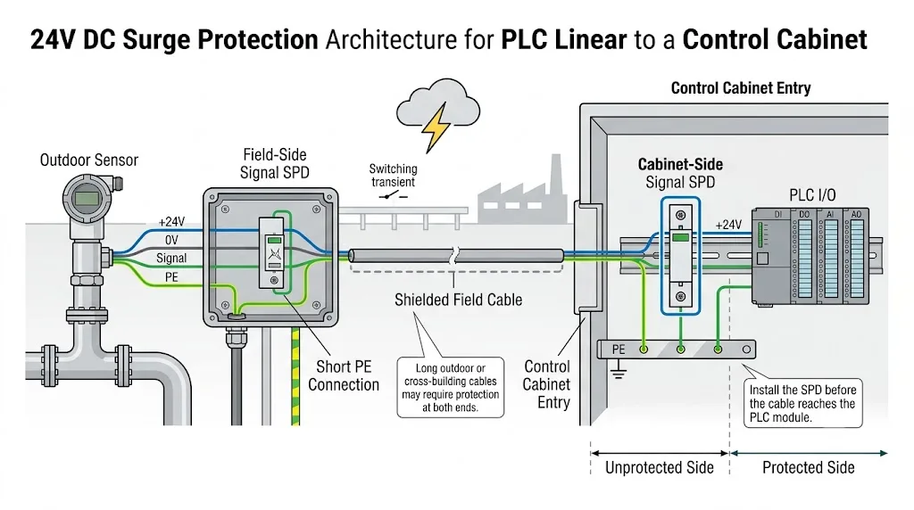
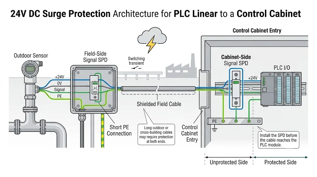
¿Instalar el SPD en el extremo del campo, en el extremo del armario o en ambos extremos?
La posición de instalación sigue la exposición del cable, el límite de la zona de protección, el valor del equipo y las condiciones de conexión a tierra locales.
| Escenario de Instalación | Decisión de Protección Típica | Razón de Ingeniería |
|---|---|---|
| Cableado corto dentro de un gabinete | A menudo, un SPD de señal dedicado no es necesario a menos que se haya identificado un riesgo transitorio interno específico. | Los conductores no cruzan un límite de protección externo ni una zona de aterrizaje separada. |
| Dispositivo interior en la misma zona equipotencial | Considere la protección de entrada al gabinete cuando el cable sea largo, expuesto o crítico para la operación. | El módulo PLC es a menudo el extremo más sensible y costoso. |
| Sensor o transmisor exterior | Considere SPDs coordinados cerca del instrumento de campo y en la entrada del gabinete. | Ambos extremos pueden estar expuestos a voltajes transitorios a lo largo del cable de campo. |
| Cable entre edificios separados | Proteja ambos extremos locales y revise el tratamiento de unión y blindaje. | Pueden ocurrir diferencias de potencial entre los dos sistemas de aterrizaje de los edificios. |
| Bucle de instrumento en área peligrosa | Utilice un SPD aprobado de manera adecuada que esté coordinado con el diseño de seguridad intrínseca. | No se debe asumir que un SPD de señal general es adecuado para un circuito Ex i. |
Coloque el SPD donde el cable de campo externo ingresa al gabinete, antes de que el cable no protegido sea direccionado a través del área del PLC. Mantenga los conductores de campo entrantes separados del cableado protegido que sale del SPD. La IEC 61643-22 aborda los principios de selección, ubicación y coordinación para SPDs de redes de señalización.[2]
Conexión a tierra y manejo de blindaje para un SPD de señal de 24V
Un producto adecuado aún puede ofrecer una protección instalada deficiente cuando su ruta de descarga es larga o cuando el cableado protegido y no protegido se dirigen juntos.
Conecte el SPD a la PE del gabinete o a la estructura de enlace equipotencial utilizando la ruta práctica más corta.
Cuando el SPD utiliza la guía de montaje como parte de su conexión PE, la guía debe estar correctamente unida a la estructura PE del gabinete.
No dirija el cableado de campo entrante junto a los conductores protegidos después del SPD.
El blindaje del cable realiza una función de EMC y no debe reemplazar la conexión a tierra del SPD.
Los pares analógicos flotantes y los circuitos digitales de referencia común pueden requerir diferentes disposiciones de protección.
La unión de escudos de un solo extremo o multipunto depende del diseño EMC y las condiciones de equipotencialidad, no de una regla universal.
Parámetros a confirmar antes de elegir el SPD
Estos parámetros determinan si el protector puede sobrevivir a la operación normal y proteger el puerto sin distorsionar la señal.
Indique la tensión normal y el valor más alto esperado, incluyendo la tolerancia de la fuente de alimentación.
Identifique DI, DO, AI, AO, 4-20mA, 0-10V, PNP, NPN u otra interfaz definida.
Confirme par flotante, referencia común y modos de protección requeridos de línea a línea y de línea a tierra.
El SPD debe transportar la corriente de bucle o carga sin sobrecalentamiento excesivo ni caída de tensión.
Incluya la resistencia del SPD en la carga completa del bucle analógico y en el cálculo del margen de tensión.
Un exceso de fuga puede afectar un umbral de entrada de PLC o introducir error en un circuito analógico sensible.
Compare la tensión de limitación del SPD con la capacidad de soporte del PLC o del dispositivo de campo.
Confirme que el SPD no atenuará ni distorsionará la señal requerida o la comunicación superpuesta.
Confirme la construcción de dos, tres o cuatro hilos, terminales comunes y canales por módulo.
Confirme la temperatura de funcionamiento, montaje, recinto, estado de área peligrosa y la documentación de estándares requeridos.
Un valor de corriente de descarga más grande no hace automáticamente que un producto sea mejor para un puerto PLC o sensor. También se deben conocer la forma de onda de prueba, el modo de protección, la tensión de limitación y las características de señal.
Ejemplos prácticos de selección de sensores y E/S de PLC de 24V
Estos ejemplos muestran por qué los circuitos con el mismo voltaje nominal de 24V pueden requerir diferentes SPD.
Transmisor exterior de dos hilos 4–20mA
- Proteja el par completo del lazo de corriente.
- Confirme la tensión de lazo más alta y la corriente máxima del lazo.
- Agregue la resistencia del SPD a los cálculos de carga de entrada del cable y del PLC.
- Confirme la compatibilidad HART cuando sea necesario.
- Considere la protección coordinada en ambos extremos de un cable expuesto.
Sensor PNP de tres hilos conectado al DI del PLC
- Identifique +24V, 0V y el conductor de salida de conmutación.
- Confirme la disposición de protección de referencia común.
- Verifique la fuga en relación con el umbral de entrada del PLC.
- Proteja los conductores externos requeridos.
- Instale el SPD en la entrada del cable del armario de control.
PLC DO Controlando un solenoide externo
- Confirme el tipo de salida, polaridad y corriente de carga.
- Proteja el cable externo largo en el límite del gabinete.
- Proporcione una supresión local adecuada para la bobina inductiva.
- No espere que el SPD de sobretensión reemplace la supresión de conmutación repetitiva.
Sensor 0–10V conectado al PLC AI
- Confirme el voltaje de señal máximo y la topología de referencia.
- Priorice la baja fuga y el bajo error de señal adicional.
- Verifique la resistencia y capacitancia en serie.
- Separar los cables protegidos y no protegidos.
- No sustituir un SPD de potencia general de 24V.
Dónde encaja el LY10 y dónde se requiere confirmación separada
LEEYEE LY10 se presenta públicamente como un protector de sobretensiones de señal de datos en riel DIN para RS485, telemetría, control remoto, PLC, sensores y líneas de comunicación industrial. La gama disponible incluye versiones de sistemas de señal de 12V, 24V y 48V.
Esto no prueba automáticamente que una versión del LY10 sea adecuada para cada circuito de sensor de 4–20mA, 0–10V, AI, AO o de tres hilos. La compatibilidad debe confirmarse con respecto a los parámetros eléctricos completos del bucle real.
Dirección del Producto Confirmada Públicamente
- Líneas de comunicación RS485 e industrial
- Señales de telemetría y control remoto
- Versiones del sistema de señal de 12V, 24V y 48V
- Instalación en serie de riel DIN
- Corriente nominal de carga listada como 500mA
- Tasa de transmisión listada hasta 10Mbps
- Pérdida de inserción listada como no más de 0.2dB
Aplicaciones que Requieren Confirmación Adicional
- Bucles de transmisores de dos hilos 4–20mA
- Entradas y salidas analógicas de 0–10V
- Bucles analógicos habilitados para HART
- Sensores PNP o NPN de tres hilos
- Salidas de PLC que llevan corriente de carga externa
- Circuitos con límites estrictos de resistencia o fuga
- Lazos de área peligrosa o intrínsecamente seguros
Errores comunes en la selección e instalación
Un protector de potencia de 24V no es automáticamente adecuado para un circuito de señal de PLC analógico o digital.
DI, DO, AI y AO pueden tener diferentes requisitos de corriente, referencia y integridad de señal.
Suposiciones incorrectas sobre fuentes, sumideros y el conductor común pueden producir la disposición de terminal incorrecta.
La resistencia añadida puede reducir el voltaje de bucle disponible o afectar el rendimiento de medición.
El cableado de campo no protegido no debe atravesar el área sensible del PLC antes de llegar al SPD.
La forma de onda, el modo de protección, el voltaje limitado y los parámetros de señal también son necesarios para una comparación significativa.
Lo que un comprador de OEM o un constructor de paneles debería confirmar
Proporcionar suficiente información del circuito para prevenir errores de modelo, terminal, etiquetado y muestreo.
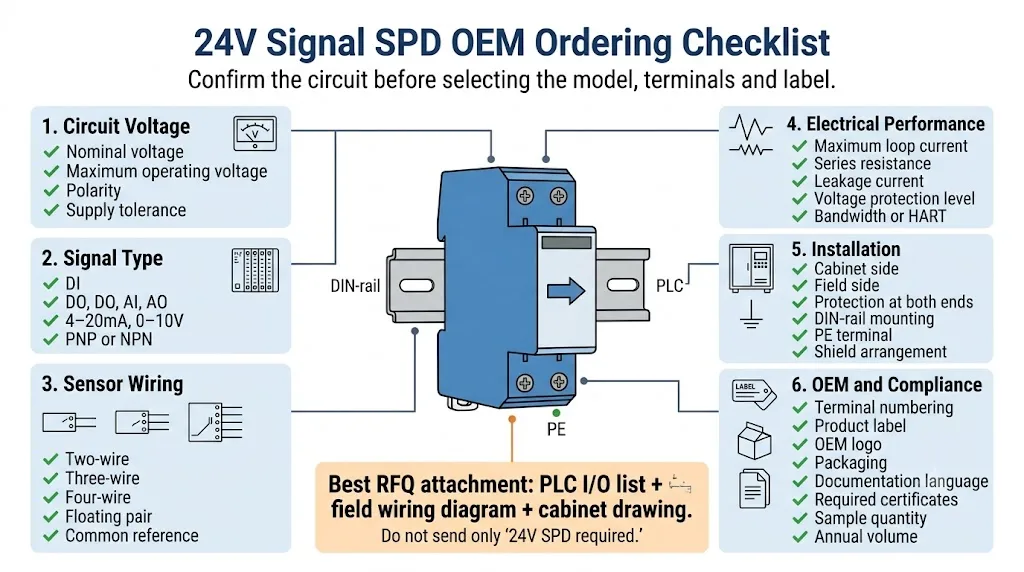
Lista de confirmación técnica y comercial.
- Voltaje nominal y máximo del circuito.
- Función DI, DO, AI o AO
- 4–20mA, 0–10V, PNP, NPN o señal de datos
- Circuito de dos, tres o cuatro hilos
- Topología flotante o de referencia común
- Corriente máxima de bucle o de carga
- Resistencia, fuga y error de señal permitidos
- Numeración de conductores, canales y terminales
- Montaje en riel DIN, gabinete o campo
- Requisitos de temperatura, zona peligrosa y aprobación
- Requisitos de logotipo, etiqueta y embalaje de OEM
- Cantidad de muestra y volumen anual estimado
Preguntas frecuentes sobre los protectores contra sobretensiones de señal de 24V
¿Cada sensor de 24V necesita un protector contra sobretensiones?
No. El cableado corto ubicado completamente dentro de un gabinete puede no necesitar un SPD de señal individual. La protección se vuelve más importante para dispositivos exteriores, cables largos, cableado entre edificios, zonas de conexión a tierra separadas y sistemas donde el tiempo de inactividad es costoso.
¿Puede un SPD de 24V proteger DI, DO, AI y AO?
No automáticamente. Los circuitos digitales y analógicos pueden tener diferentes topologías, corrientes, fugas, resistencias, capacitancias y requisitos de integridad de señal. Confirma la función I/O exacta antes de seleccionar el modelo.
¿Puede un SPD de 24V DC proteger un bucle de 4–20mA?
No debe asumirse. Un bucle de 4–20mA requiere un protector de señal seleccionado para el voltaje del bucle, corriente, resistencia, fuga, voltaje limitante y requisitos de comunicación.
¿Afectará un SPD a una medición de 4–20mA?
Puede hacerlo cuando su resistencia en serie o corriente de fuga no sean adecuadas. Incluye la resistencia del SPD en el cálculo de carga del transmisor, cable y entrada del PLC y verifica que quede un margen de voltaje del bucle adecuado.
¿Dónde debe instalarse el SPD en un armario de PLC?
Instálalo en el límite de entrada del cable externo antes de que el cableado de campo llegue a los terminales I/O del PLC. Mantén la conexión PE corta y separa el cableado de campo entrante del lado protegido.
¿Es el LY10 adecuado para cada circuito de E/S de 24V PLC?
No se debe suponer una idoneidad universal. LY10 está posicionado públicamente para líneas de comunicación industrial RS485 y compatibles. Un circuito de 4–20mA, 0–10V, AI, AO, PNP o NPN requiere confirmación en función de los parámetros eléctricos reales.
Mantener cada tema de protección separado
Utilice esta página para señales I/O de sensores y PLC de 24V. Utilice las guías relacionadas para la arquitectura completa del panel de control y el cableado de comunicación RS485.
Referencias técnicas
- IEC 61643-21:2025, dispositivos de protección contra sobretensiones conectados a redes de telecomunicaciones y señalización—requisitos y métodos de prueba. Página de publicación IEC .
- IEC 61643-22:2015, selección, operación, ubicación y principios de coordinación para dispositivos de protección contra sobretensiones conectados a redes de telecomunicaciones y señalización. Página de publicación IEC .
- IEC 61000-4-5:2014+A1:2017, compatibilidad electromagnética pruebas de inmunidad a sobretensiones y técnicas de medición. Página de publicación IEC .
- Phoenix Contact, protección contra sobretensiones para medición, control y tecnología de señal, incluidos circuitos de señal analógica y de referencia común. Página técnica de Phoenix Contact .
- Weidmüller, protección contra sobretensiones para circuitos de instrumentación y control, incluidos señales analógicas y binarias. Página técnica de Weidmüller .
- Información del producto del protector contra sobretensiones de señal de datos de riel DIN LEEYEE LY10. Página del producto LEEYEE .
¿Necesita un SPD de señal de 24V para un circuito de E/S de PLC real?
Envíe la lista de I/O del PLC, cableado de sensores, tensión máxima del circuito, corriente de carga o bucle, longitud del cable y disposición de conexión a tierra. LEEYEE separará primero los requisitos de alimentación, I/O digital, bucle analógico y comunicación antes de confirmar un modelo.
