
La protección contra sobretensiones en torres de comunicación debe abarcar todo el sitio de radio, no solo un SPD dentro de un gabinete exterior. El mismo principio a nivel de sitio se aplica a la protección contra sobretensiones de sitios celulares, la protección contra rayos de torres de telecomunicaciones y muchas instalaciones de estaciones base de radio.
La estructura de la torre, la alimentación de CA, los alimentadores de −48 V CC, las interfaces de antena, las líneas de datos de cobre, los gabinetes de equipos y la red de puesta a tierra del sitio deben funcionar como un sistema de protección coordinado.
Índice
Respuesta rápida
Un sitio de torre de comunicación normalmente necesita cuatro funciones coordinadas: un sistema de protección externa contra rayos, un sistema de puesta a tierra del sitio, enlace equipotencial y SPDs seleccionados correctamente en líneas de potencia y señal conductivas.[1][2]
La alimentación de CA, −48 V CC, alimentadores de RF o coaxiales, Ethernet, PoE y líneas de control requieren diferentes dispositivos de protección. Cada SPD debe coincidir con el circuito real, el límite de instalación y la exposición esperada a sobretensiones.
Significado para el comprador: enviar al proveedor la arquitectura del sitio, los voltajes operativos, la disposición de puesta a tierra, las interfaces de cable y las posiciones de SPD propuestas. Una solicitud de solo “un SPD para una torre de comunicación” no es suficiente para una selección confiable.
Cómo trabajan juntos la protección contra rayos y sobrevoltajes de torres de comunicación
Un impacto directo puede enviar corriente a través de la estructura de la torre, la red de tierra, las mallas de los cables y los servicios conectados. Por lo tanto, el equipo electrónico puede dañarse incluso cuando el rayo no golpea directamente un puerto del equipo.
ITU-T K.112 proporciona procedimientos prácticos para la protección contra rayos, la puesta a tierra y la unión en estaciones base de radio independientes y en azoteas.[2] ITU-T K.119 evalúa cuatro partes conectadas del sistema de protección.[3]
Terminación aérea y camino de corriente
El sistema externo intercepta rayos directos y proporciona un camino diseñado hacia la tierra.
Sistema de puesta a tierra del sitio
La torre, el refugio y las estructuras asociadas se conectan a una red de terminación a tierra coordinada.
Unión equipotencial
Las estructuras metálicas, las mallas de cables, los bastidores de equipos y los conductores de protección se coordinan para limitar las diferencias de potencial.
Dispositivos de protección contra sobrevoltajes
Los SPDs limitan los picos conducidos en circuitos de CA, CC, RF, datos y control en los límites relevantes.
¿Qué incluye una arquitectura de protección completa para un sitio de torre?
Comience con el sitio físico en lugar de un catálogo de productos. Trace las rutas esperadas de corriente de rayo, identifique cada cable conductor que cruce un límite de protección y asigne la función de protección adecuada a esa ubicación.
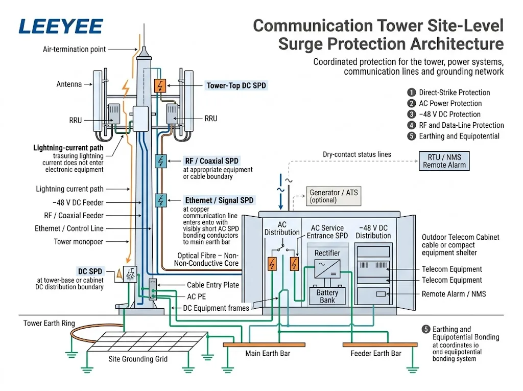
- Evalúe la torre y su exposición a rayos. Confirme si la instalación es una torre independiente, un sitio en azotea, un monopolo, un mástil de transmisión o una estación inalámbrica remota. La IEC 62305-2 proporciona un procedimiento de gestión de riesgos para seleccionar medidas de protección apropiadas.[5]
- Defina el sistema de protección contra rayos externo. Confirme el arreglo de terminación de aire, el camino de corriente, la terminación a tierra, los requisitos de separación y la protección contra voltajes de contacto y de paso.[6]
- Establezca el concepto de unión del sitio. Identifique la estructura de acero de la torre, el armario, el refugio, la placa de entrada de cables, las barras a tierra del alimentador, el PE de CA, los marcos de equipos de CC y los racks de equipos de radio.
- Mapee cada servicio conductor. Incluya CA de utilidad, generadores, -48 V CC, alimentadores coaxiales, Ethernet, PoE, RS485, AISG, líneas de alarma, sensores y circuitos de iluminación de torres.
- Marque cada límite de protección. Identifique dónde los cables entran o salen de un área equipotencial y dónde está conectado el equipo sensible.
- Seleccione y coordine los SPD. Utilice el estándar de SPD aplicable de CA, CC o telecomunicaciones y verifique los parámetros requeridos en cada posición.[8][9][11][12]
- Planifique la puesta en marcha y el mantenimiento. Mantenga accesibles para inspección los indicadores, contactos remotos, puntos de unión y módulos reemplazables.
¿Dónde pueden ingresar las sobrecargas a un sitio de torre de comunicación?
La torre es el punto de exposición más visible, pero no es la única vía. Toda conexión conductora entre el equipo exterior, la torre, la fuente de alimentación, el gabinete y la electrónica sensible requiere revisión.
| Vía de entrada | Exposición típica | Función de protección | El comprador debe confirmar |
|---|---|---|---|
| Torre o mástil | Impacto directo y flujo de corriente de rayo a través de la estructura | LPS externo, trayectoria de corriente, terminación a tierra y equipotencialidad | Tipo de torre, altura, disposición, evaluación de riesgo y diseño del LPS |
| Suministro de CA | Línea de alimentación, tramo aéreo, generador, ATS o distribución del sitio | SPD de CA coordinado con el suministro y la exposición al rayo | Tensión, fases, sistema de puesta a tierra, Uc, Iimp o In, Up y protección de respaldo |
| Alimentador de −48 V CC | Alimentador de cobre largo entre el rectificador, la distribución de CC y la radio montada en la torre | SPD de CC de baja tensión en los límites de protección requeridos | Tensión máxima del bus, polaridad, unión, modos de protección y posiciones del SPD |
| Línea de RF o coaxial | Alimentador de antena metálico, conector y blindaje del cable | SPD de RF y unión del blindaje en el límite diseñado | Conector, impedancia, frecuencia, potencia de RF, pérdida de inserción y ROE |
| Ethernet o PoE | Cable de red de cobre exterior entre distintas áreas de equipos | SPD para línea de datos adaptado al rendimiento de Ethernet y PoE | Tasa de datos, tipo de PoE, potencia, pares protegidos y apantallamiento |
| Línea de control o alarma | RS485, AISG, sensor, contacto seco o circuito de luz de navegación | SPD de señal seleccionado para el circuito operativo real | Tensión, protocolo, número de pares, corriente y disposición de terminales |
Una fibra óptica totalmente dieléctrica no conduce corriente de sobretensión a través de la fibra de vidrio. La armadura metálica, los elementos de refuerzo, los conductores de potencia híbridos, las carcasas de los equipos y los circuitos de cobre asociados siguen requiriendo evaluación.
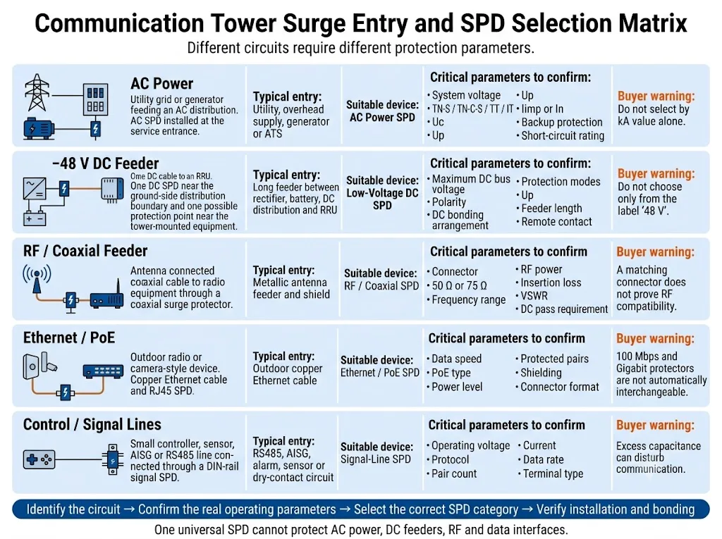
Conclusión de compras: identifique el circuito antes de comparar las corrientes nominales de descarga. Un valor kA elevado o un conector coincidente no demuestran compatibilidad con la tensión de funcionamiento, el modo de protección, la frecuencia ni el rendimiento de datos.
¿Cómo debe protegerse la entrada de CA?
La disposición de protección de CA depende de la exposición de la torre, la alimentación de entrada, el sistema externo de protección contra el rayo y la distribución aguas arriba.
Una torre autónoma con un servicio de entrada expuesto puede requerir una solución distinta de la de los equipos en azotea alimentados a través de un sistema de distribución de edificio protegido.
IEC 61643-11:2025 especifica requisitos y métodos de ensayo para los SPD conectados a sistemas de alimentación de baja tensión en CA.[9] IEC 61643-12:2020 trata la selección, el funcionamiento, la ubicación y la coordinación de SPD de CA.[10]
Confirme estos parámetros de CA
- Tensión del sistema y Uc: utilice la tensión máxima real de funcionamiento continuo, no solo la denominación nominal de la red.
- Sistema de conexión a tierra: Las configuraciones TN-S, TN-C-S, TT e IT pueden requerir distintos modos de protección.
- Exposición a corriente de rayo: Confirme si se requiere Tipo 1, Tipo 1+2 u otra disposición coordinada.
- Nivel de protección de tensión: coordine Up con el nivel de soportabilidad del equipo y la protección aguas abajo.
- Parámetros de descarga: confirme Iimp, In o Imax según la clasificación del SPD y el requisito del proyecto.
- Condiciones de cortocircuito: verifique la corriente de cortocircuito presunta, la capacidad de cortocircuito del SPD y la protección de respaldo.
- Vías de alimentación alternativas: incluya generadores, circuitos ATS y cualquier otra fuente conectada.
- Ruta de conexión: mantenga la conexión completa del SPD lo más corta y directa posible porque la inductancia del conductor añade tensión durante una sobretensión rápida.
¿Cómo debe protegerse el alimentador de −48 V CC?
Los emplazamientos de radio suelen utilizar rectificadores y baterías para alimentar los equipos de radio instalados en la torre mediante largos alimentadores de CC de cobre. Una sobretensión transitoria puede entrar desde el lado de la torre o aparecer debido a una diferencia de potencial entre los equipos de la torre y los equipos situados a nivel del suelo.
La norma IEC 61643-41:2025 se aplica a los DPS conectados a circuitos de alimentación de CC y a equipos con una tensión nominal de hasta 1,500 V CC.[11] No obstante, el dispositivo seleccionado debe estar diseñado y especificado para el circuito de telecomunicaciones de baja tensión real.
No seleccione basándose únicamente en la etiqueta “48 V”
El bus de CC puede superar su valor nominal durante el funcionamiento del rectificador, la carga de la batería o los ajustes del sistema. Confirme la tensión máxima de funcionamiento continuo antes de fijar la tensión nominal del DPS.
| Pregunta sobre CC | Por qué es importante | Información que se debe proporcionar |
|---|---|---|
| Tensión máxima del bus | Una tensión continua inadecuada puede provocar un envejecimiento prematuro o un nivel de protección inapropiado. | Rango del rectificador, tensión de flotación de la batería, tensión de carga y límites de funcionamiento anormal. |
| Configuración de la conexión equipotencial de CC | Los modos de protección dependen de la relación entre CC+, retorno, CC− y PE. | Diagrama unifilar y configuración de conexión equipotencial o puesta a tierra del proyecto. |
| Exposición del alimentador | Un alimentador largo que atraviesa distintas áreas de equipos puede requerir una protección coordinada en más de un límite. | Longitud del alimentador, recorrido, altura de la torre, ubicaciones de las radios y posiciones propuestas de los DPS. |
| Supervisión del estado | Una avería en un emplazamiento no atendido puede pasar inadvertida sin una señal remota. | Contacto NO, NC o conmutado requerido y lógica de alarma de la RTU o del NMS. |
¿Cómo deben protegerse las líneas de RF, Ethernet y control?
Cada protector debe preservar el funcionamiento normal de su circuito mientras limita la tensión transitoria. Un dispositivo puede encajar mecánicamente y seguir siendo eléctricamente inadecuado.
Alimentadores de RF y coaxiales
Confirme el tipo de conector, la impedancia característica, la frecuencia de funcionamiento, la potencia de RF, la pérdida de inserción, la pérdida de retorno o VSWR, el requisito de paso de CC y la clasificación ambiental.
La pantalla del cable y el protector de RF deben conectarse equipotencialmente en la posición requerida por el diseño del sitio. La protección o la conexión equipotencial en ambos extremos puede ser adecuada en algunas arquitecturas, pero no es una regla universal.
Ethernet y PoE
IEC 61643-21:2025 cubre los SPD para redes de telecomunicaciones y señalización, incluidas las redes que suministran energía por la misma línea, como PoE.[12]
Confirme la velocidad de Ethernet, el tipo de PoE, la potencia máxima, los pares protegidos, el apantallamiento y el rendimiento de inserción aceptable. No debe suponerse que un dispositivo diseñado para 100 Mbps o PoE de menor potencia sea adecuado para Ethernet Gigabit o PoE de mayor potencia.
Circuitos RS485, AISG, de alarma y de sensores
Adapte el SPD a la tensión de funcionamiento, el nivel máximo de señal, el número de conductores, la corriente, la velocidad de datos, el conductor de referencia y la disposición de los terminales.
Una capacitancia excesiva o un nivel de protección inadecuado pueden perturbar la comunicación incluso cuando el propio SPD siga operativo.
¿Por qué la puesta a tierra y el enlace equipotencial determinan el resultado?
Un SPD desvía la corriente de sobretensión hacia la red de conexión equipotencial y puesta a tierra. Si ese recorrido es largo, indirecto, corroído o está mal coordinado, la tensión en el equipo protegido puede ser significativamente superior al valor Up indicado en la ficha técnica del SPD.
La conexión equipotencial del sitio no consiste simplemente en un conjunto de picas de tierra. Su objetivo es reducir las diferencias de potencial peligrosas entre la torre, el armario, el refugio, las pantallas de los cables, el PE de CA, los equipos de CC y otros sistemas conductores durante un evento de rayo.[2][7]
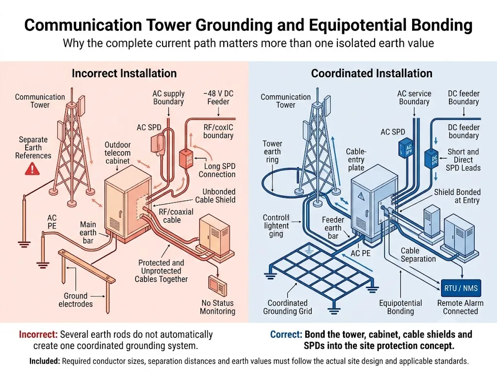
Un único valor de resistencia de tierra no es la respuesta completa
La resistencia de tierra es importante, pero el resultado también depende de las rutas de los conductores, la inductancia, la geometría de la red, las condiciones del suelo, la distribución de la corriente, la calidad de las conexiones, la corrosión y la posición de la conexión equipotencial.
No prometa que todas las torres están protegidas cuando la resistencia medida es inferior a un valor fijo. Los criterios de aceptación deben ajustarse a las especificaciones del sitio, las normativas locales, el método de medición y un diseño cualificado de protección contra rayos.
Puntos de equipotencialidad que normalmente requieren revisión
- Estructura de acero de la torre, monopolo o mástil.
- Conductores de bajada externos instalados por separado.
- Barra de tierra de la base de la torre y barra principal de equipotencialidad de la sala de equipos.
- Bastidor del gabinete exterior, puerta, placa de entrada de cables y barra PE interna.
- Pantallas de los cables coaxiales y barras de tierra de los alimentadores.
- PE de CA, puesta a tierra del generador y equipotencialidad relacionada con el ATS.
- Rectificador, bastidor de baterías, distribución de CC y bastidores de telecomunicaciones.
- Bandejas portacables metálicas, cercas y equipos auxiliares de la torre cuando el diseño lo requiera.
¿Por qué es crítica la frontera entre la torre y el gabinete?
El punto donde los cables salen de la torre y entran en un armario o refugio exterior combina conductores expuestos, pantallas de cables, conexiones equipotenciales y puertos electrónicos sensibles.
- Coloque el SPD adecuado cerca de la entrada de cables o del límite del equipo correspondiente.
- Conecte las pantallas de los cables a la barra de tierra del alimentador o al punto de entrada definido por el diseño del emplazamiento.
- Utilice conductores de conexión del SPD cortos y directos.
- Separe las secciones de cable protegidas y no protegidas para reducir el reacoplamiento de sobretensiones.
- Evite bucles innecesarios, cambios bruscos de recorrido y longitudes excesivas de conductor.
- Integre la torre, el armario y el refugio en el sistema coordinado de conexiones equipotenciales del emplazamiento.
- Mantenga accesibles los indicadores, los módulos reemplazables y los terminales remotos después de la instalación.
¿Cómo deben planificarse la alarma remota y el mantenimiento?
Muchas torres de comunicaciones se encuentran en ubicaciones remotas o no cuentan con personal permanente. Un módulo averiado, un conductor de conexión desconectado o una conexión corroída pueden pasar desapercibidos hasta que se produzca otro evento de sobretensión.
La norma ITU-T K.119 aborda la inspección visual, la medición, el análisis y otros métodos utilizados para evaluar la fiabilidad de los sistemas de protección contra el rayo y de puesta a tierra de las estaciones base de radio.[3] La norma IEC 62305-4 también contempla la inspección, el mantenimiento y las pruebas de las medidas de protección contra sobretensiones.[7]
La supervisión remota puede informar sobre
- El estado normal o de fallo del módulo SPD.
- La extracción del módulo cuando el mecanismo del SPD lo permite.
- El estado del contacto seco NO, NC o conmutado.
- Una entrada de alarma a una RTU, un PLC, un controlador de armario o un sistema de gestión de red.
La indicación remota facilita el mantenimiento, pero no sustituye la inspección física. Es posible que un único contacto auxiliar no detecte la corrosión, los conductores flojos, los daños en la envolvente ni los módulos de reemplazo incorrectos.
Inspeccione el sistema de protección
- Durante la puesta en servicio y la aceptación iniciales.
- En el intervalo programado de mantenimiento preventivo.
- Después de un evento de rayo registrado o de una falla inexplicable del equipo.
- Después de añadir antenas, radios, equipos de alimentación u otro gabinete.
- Después de realizar trabajos de puesta a tierra, obras civiles o cambios en las rutas de cables.
- Cuando un indicador de SPD o una alarma remota cambie de estado.
¿Cómo cambia el tipo de sitio la decisión de protección?
Torre independiente con sistema de puesta a tierra
Este sitio normalmente cuenta con su propia torre, red de puesta a tierra, suministro eléctrico de la red o de un generador, envolvente para equipos y varios conductores de cobre expuestos. Puede requerir protección contra impactos directos, además de SPD coordinados para líneas de CA, CC, RF y señal.
Instalación de radio en azotea
Los equipos instalados en la azotea comparten el sistema de protección contra rayos del edificio, el terminal principal de puesta a tierra y la distribución eléctrica. El diseñador debe revisar la distancia de separación, las zonas de protección y la coordinación con los SPD existentes del edificio.
Sitio remoto de microondas o monitoreo
Este sitio puede utilizar baterías, energía solar, una pequeña fuente de CA, líneas Ethernet o de control de gran longitud y acceso limitado para mantenimiento. La selección debe seguir las interfaces conductoras reales y la arquitectura de alimentación.
Conclusión de ingeniería: “torre de comunicaciones” no identifica un paquete universal de SPD. El sitio físico y la arquitectura de cableado determinan qué funciones de protección se requieren.
¿Cómo debe un comprador verificar el paquete SPD propuesto?
Los diagramas explican el concepto de protección, pero no constituyen aprobaciones de productos. Antes de aprobar un paquete para un sitio de torre, verifique cada modelo propuesto con respecto al circuito que protegerá.
Solicite evidencia específica del modelo
LEEYEE es un proveedor especializado en protección contra sobretensiones y protección de baja tensión. CNSPD es la plataforma de LEEYEE centrada en la protección contra sobretensiones para compradores técnicos de todo el mundo.
Un certificado para una serie o configuración no debe considerarse automáticamente como una aprobación para todas las tensiones, disposiciones de polos, conectores o variantes OEM. Confirme el alcance exacto del documento antes de presentar el proyecto.
¿Qué debe confirmarse antes de realizar un pedido?
Prepare la siguiente información antes de solicitar recomendaciones de modelos, muestras, archivos técnicos o una cotización OEM.
Solicitar una revisión de configuración de SPD para torre de comunicación
Comparta el diagrama unifilar del sitio, la disposición de la torre y el armario, los detalles del suministro de CA, el voltaje máximo del bus de CC, las interfaces de cable y el plano de puesta a tierra con LEEYEE.
Los modelos propuestos y las posiciones de instalación deben confirmarse de acuerdo con las instrucciones reales del equipo, las normativas eléctricas locales, las especificaciones del proyecto y un diseño de protección contra rayos cualificado.
Preguntas frecuentes sobre la protección contra sobretensiones en torres de comunicación
¿Puede un único SPD de CA proteger todo el sitio de la torre de comunicación?
¿Requiere toda torre de comunicación un SPD de Tipo 1?
¿Dónde debe instalarse el SPD de −48 V CC?
¿Puede utilizarse un SPD de CC para fotovoltaica en un sistema de telecomunicaciones de 48 V?
¿Elimina la fibra óptica la necesidad de protección contra sobretensiones?
¿Debe instalarse un protector contra sobretensiones de RF en ambos extremos del cable?
¿Es suficiente un valor bajo de resistencia de puesta a tierra?
¿Es útil una alarma remota en una torre de telecomunicaciones?
¿Qué documentos debe solicitar un comprador OEM?
Referencias
- Unión Internacional de Telecomunicaciones, UIT-T K.56 (05/2021), Protección de estaciones base de radio contra descargas atmosféricas. Publicación oficial de la UIT.
- Unión Internacional de Telecomunicaciones, UIT-T K.112 (05/2021), Protección contra rayos, puesta a tierra y equipotencialidad: Procedimientos prácticos para estaciones base de radio. Publicación oficial de la UIT.
- Unión Internacional de Telecomunicaciones, ITU-T K.119 (12/2016), Evaluación de la conformidad de estaciones base de radio en relación con la protección contra rayos y la puesta a tierra. Publicación oficial de la UIT.
- Comisión Electrotécnica Internacional, IEC 62305-1:2024, Protección contra el rayo – Parte 1: Principios generales. Publicación oficial de IEC.
- Comisión Electrotécnica Internacional, IEC 62305-2:2024, Protección contra el rayo – Parte 2: Gestión del riesgo. Publicación oficial de IEC.
- Comisión Electrotécnica Internacional, IEC 62305-3:2024, Protección contra el rayo – Parte 3: Daño físico a estructuras y riesgo humano. Publicación oficial de IEC.
- Comisión Electrotécnica Internacional, IEC 62305-4:2024, Protección contra el rayo – Parte 4: Sistemas eléctricos y electrónicos en estructuras. Publicación oficial de IEC.
- Comisión Electrotécnica Internacional, IEC 61643-01:2024, Dispositivos de protección contra sobretensiones de baja tensión – Parte 01: Requisitos generales y métodos de ensayo. Publicación oficial de IEC.
- Comisión Electrotécnica Internacional, IEC 61643-11:2025, Dispositivos de protección contra sobretensiones de baja tensión – Parte 11: Dispositivos de protección contra sobretensiones conectados a sistemas de potencia de baja tensión de CA – Requisitos y métodos de ensayo. Publicación oficial de IEC.
- Comisión Electrotécnica Internacional, IEC 61643-12:2020, Dispositivos de protección contra sobretensiones de baja tensión – Parte 12: Dispositivos de protección contra sobretensiones conectados a sistemas de potencia de baja tensión – Principios de selección y aplicación. Publicación oficial de IEC.
- Comisión Electrotécnica Internacional, IEC 61643-41:2025, Dispositivos de protección contra sobretensiones de baja tensión – Parte 41: Dispositivos de protección contra sobretensiones conectados a sistemas de alimentación de CC de baja tensión – Requisitos y métodos de ensayo. Publicación oficial de IEC.
- Comisión Electrotécnica Internacional, IEC 61643-21:2025, Dispositivos de protección contra sobretensiones de baja tensión – Parte 21: Dispositivos de protección contra sobretensiones conectados a redes de telecomunicaciones y señalización – Requisitos y métodos de ensayo. Publicación oficial de IEC.
- Comisión Electrotécnica Internacional, IEC 61643-31:2018, Dispositivos de protección contra sobretensiones de baja tensión – Parte 31: Requisitos y métodos de ensayo para dispositivos de protección contra sobretensiones (SPD) para instalaciones fotovoltaicas. Publicación oficial de IEC.
