
Un UPS no es un sustituto de una estrategia completa de SPD. Los niveles de protección correctos dependen del diagrama unifilar real, el sistema de puesta a tierra, la exposición a rayos, la corriente de cortocircuito prospectiva, la topología del UPS, la distancia del cable, la redundancia A/B y los requisitos de resistencia del equipo.
Índice
Por qué la protección contra sobretensiones en centros de datos requiere múltiples niveles coordinados
Los centros de datos contienen varias capas de conversión de energía, transferencia, distribución y comunicación. Un transitorio puede entrar a través de un servicio externo, ser inducido en un conductor largo o originarse en equipos de conmutación dentro de la instalación.
Exposición a sobretensiones externas
Los efectos de los rayos y las perturbaciones de conmutación de la utilidad pueden ejercer estrés transitorio en el conmutador de entrada, el equipo ATS, las entradas del SAI y los circuitos de control conectados.
Eventos de conmutación internos
Los generadores, la operación del ATS, los enfriadores, los motores, los VFD, los contactores y los eventos de bypass del SAI pueden crear o redistribuir sobrevoltajes transitorios dentro de la instalación.
Caminos de entrada de cobre en paralelo
El cableado de Ethernet, PoE, BMS, DCIM y sensores puede llevar una sobretensión al equipo, incluso cuando el sistema de distribución de CA ya incluye SPDs.
Un SAI apoya la continuidad del suministro de energía y las condiciones de calidad de energía especificadas. Un SPD limita las sobrevoltajes transitorios de corta duración y desvía la corriente de sobretensión. La protección interna del SAI varía según el modelo y la topología, por lo que la entrada principal, el bypass y la distribución aguas abajo deben seguir siendo revisados.
La IEC 61643-11 define los requisitos y métodos de prueba para los SPD conectados a sistemas de energía de baja tensión en CA. La IEC 61643-12 aborda la selección, operación, ubicación y coordinación. Por lo tanto, un diseño confiable requiere tanto un SPD adecuado como una instalación coordinada. [1] [2]
Arquitectura de protección contra sobretensiones en centros de datos
Comience con cada camino de energía y comunicación de cobre. No empiece seleccionando un modelo de SPD y luego buscando un lugar para instalarlo.
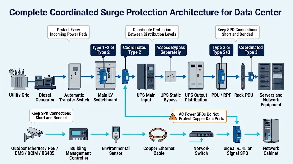
Controlar la energía entrante
Evalúe el servicio público, fuente del generador, ATS y el tablero de distribución de baja tensión principal para la capacidad de sobretensión que puede alcanzar la instalación.
Coordinar la protección aguas abajo
Revise la entrada del UPS, bypass, distribución de salida, PDU y RPP de acuerdo con la distancia, topología y el estrés de voltaje restante.
Proteger interfaces de cobre
Las líneas RJ45, PoE, RS485, Modbus y de sensores requieren protección específica para la interfaz. Un SPD de energía en CA no puede proteger directamente estos puertos.
Un SPD en el camino de energía A no protege automáticamente el camino de energía B. Confirme la fuente, UPS, bypass, distribución aguas abajo y alimentación del estante a cada lado bajo condiciones normales, de falla y de mantenimiento.
¿Dónde se instalan los SPD en un centro de datos?
La tabla proporciona un punto de partida práctico. No trata una calificación de corriente de descarga fija como correcta para cada centro de datos.
| Punto de instalación | Objetivo de protección | Punto de partida común | Confirme antes de ordenar |
|---|---|---|---|
| Entrada de servicio o tablero de distribución LV principal | Limitar los picos de alta energía que entran en la instalación de bajo voltaje. | Tipo 1+2 donde se aplica la carga de corriente de rayo. El Tipo 2 puede aplicarse donde no se requiere la carga de Tipo 1. | LPS externo, exposición al servicio, evaluación de riesgos, sistema de puesta a tierra, Uc, Iimp, Up, corriente de fallo y protección de respaldo. |
| Secciones de generador o ATS | Proteger las entradas de fuente, equipo de transferencia y controladores sensibles. | SPD de potencia coordinado según el camino de la fuente y el límite de la zona de protección. Proteger la señal por separado donde sea necesario. | Enrutamiento de utilidad y generador, disposición del ATS, voltaje del controlador, conductores expuestos y posición del SPD ascendente. |
| Entrada principal de UPS | Proteger el equipo de conmutación de entrada, el rectificador y otros componentes de UPS orientados hacia arriba. | Tipo 2 coordinado en muchas ubicaciones internas. El Tipo 1+2 puede aplicarse donde permanezca la carga de corriente de rayo. | Voltaje de UPS, topología, distancia ascendente, exposición a la fuente, Uc, Up, corriente de fallo y requisitos del fabricante de UPS. |
| Bypass estático o de mantenimiento | Prevenir que una ruta de bypass no protegida alcance las cargas a monte. | Evaluar como un camino separado cuando se suministre de manera independiente o evite el punto de entrada protegido del UPS. | Fuente común o separada, disposición de conmutación, estado de mantenimiento y coordinación ascendente. |
| Distribución de salida de UPS | Limitar el estrés transitorio residual o recién introducido antes de los paneles a monte. | Protección adicional de Tipo 2 donde la topología, distancia, exposición o requisitos del equipo justifican otro nivel de protección. | Aislamiento de salida, disposición de neutro, longitud del conductor, inmunidad a monte e integración de protección. |
| PDU de piso, PDU de fila o RPP | Proporcionar coordinación local para circuitos de rama y cargas de IT sensibles. | Tipo 2 o Tipo 2+3 coordinado según el requisito de sobretensión restante. | Voltaje, disposición de fase, distancia, Up, corriente de falla de rama, espacio de alojamiento y alarma remota. |
| Rack PDU o punto de uso | Reducir el estrés transitorio residual cerca de equipos sensibles. | Tipo 3 o protección a nivel de equipo como la última parte de un sistema coordinado aguas arriba. | Protección integrada, posibilidad de reemplazo, indicación de estado, calificación de carga y coordinación aguas arriba. |
| RJ45, PoE, BMS, DCIM y líneas de señal | Detener las sobretensiones que ingresan a través de interfaces de comunicación y control de cobre. | SPD específico de interfaz destinado a redes de telecomunicaciones o señalización. | Tensión de trabajo, asignación de pines, tasa de datos, estándar PoE , corriente, pérdida de inserción, apantallamiento y conexión a tierra. |
El SPD debe coincidir con su punto de instalación, tensión, sistema de puesta a tierra, deber de sobretensión esperado, nivel de protección de voltaje, condiciones de falla, protección de respaldo, cubierta y estrategia de mantenimiento.
Protección del tablero eléctrico principal de baja tensión, generador y ATS
Tablero general de baja tensión
El tablero principal suele ser la primera ubicación evaluada para protección contra sobretensiones de alta energía. Las palabras “centro de datos” solas no determinan si el SPD debe ser Tipo 1, Tipo 2 o combinado Tipo 1+2.
Confirma:
- Si el edificio tiene un sistema de protección contra rayos externo.
- Si un servicio expuesto puede conducir corriente de rayos hacia la estructura.
- La evaluación de riesgo eléctrico y de rayos aplicable.
- Si el sistema es TN-S, TN-C-S, TT o IT.
- Voltaje de operación de fase a neutro y de fase a fase.
- Corriente de cortocircuito potencial en la ubicación del SPD.
- Coordinación de fusibles o interruptores automáticos requeridos.
Ver el Guía de Selección de SPD Uc para lógica de selección de voltaje.
Rutas de generador y ATS
Un ATS puede conectar energía de red, energía de generador y distribución posterior a través de diferentes conductores y posiciones de interruptor. Sigue cada fuente en lugar de asumir que un SPD cubre cada condición de operación.
- Revisa la ruta del lado de la utilidad.
- Revisa la ruta del lado del generador.
- Revisa la salida del ATS y el panel descendente.
- Revisa los circuitos del controlador, monitoreo y comunicación del ATS.
Esto no significa que cada ATS necesite un SPD en cada terminal. Significa que cada ruta de potencia y control activa debe ser incluida en la evaluación de ingeniería.
El arreglo correcto de 3+1, 4+0, 3P+N u otro depende del sistema de puesta a tierra y el diseño del proyecto. Revise el Guía de cableado de SPD TN-S antes de confirmar el arreglo de polos.
Protección SPD del centro de datos para entrada, bypass y salida de UPS
“Instale un SPD antes y uno después de cada UPS” no es una regla de diseño completa. La respuesta depende de cómo se abastece la UPS, cómo se organiza su bypass, si la salida está aislada y cómo se distribuye el sistema aguas abajo.
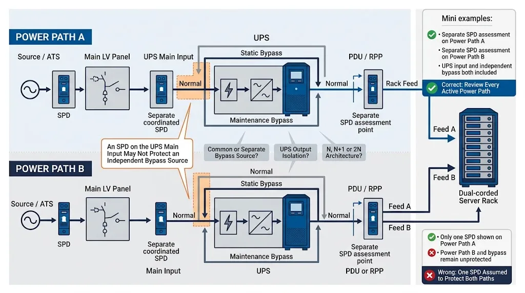
Entrada principal de UPS
El SPD de entrada ayuda a proteger el equipo de conmutación de entrada de la UPS, el rectificador y los componentes relacionados. Debe coordinarse con la SPD del cuadro principal y seleccionarse para el sistema de entrada de la UPS real.
Bypass estático
Si el bypass tiene una fuente separada o evita el punto de entrada principal protegido, requiere su propia evaluación. De lo contrario, una transitoria puede alcanzar la carga a través de la ruta de bypass.
Bypass de mantenimiento
Revise la condición eléctrica cuando la UPS esté aislada. La operación de mantenimiento no debe eliminar involuntariamente el único nivel de protección efectivo del camino crítico.
Qué revisamos en un diagrama unifilar de centro de datos
Un diagrama unifilar proporciona más información útil que una consulta que solo indica “400 V, Tipo 2, 40 kA.” Estas son las primeras condiciones que deben verificarse antes de recomendar un SPD para el centro de datos.
- Si la entrada principal de la UPS y el bypass utilizan una fuente común o separada.
- Si la Ruta de Potencia A y la Ruta de Potencia B permanecen independientes en cada modo de operación.
- Distancia entre el SPD del cuadro principal y la entrada de la UPS.
- Si la salida de la UPS crea una nueva disposición de neutro o conexión a tierra.
- Si un PDU contiene un transformador de aislamiento o SPD integrado.
- Corriente de corto circuito prospectiva y dispositivo de protección aguas arriba en cada ubicación de SPD propuesta.
- Cómo se conectarán los contactos de alarma remota al BMS o al DCIM.
- Si un módulo puede ser aislado y reemplazado sin deshabilitar ambos caminos de alimentación redundantes.
- Si las líneas PoE, Ethernet, RS485 o de sensores expuestas eluden el sistema de protección AC.
- Si los Uc, Up, Iimp, In y Imax especificados se refieren a la clase de prueba y modo de protección correctos.
Marcar cada ubicación de SPD propuesta y añadir la tensión del sistema, disposición de conexión a tierra, dispositivo de protección aguas arriba, corriente de falla, trayectoria de la UPS, distancia aguas abajo y equipo conectado.
Ejemplo: Centro de datos 400/230 V TN-S con caminos duales de UPS
Este ejemplo muestra el proceso de decisión. No es una especificación universal y no reemplaza el cálculo final del diseñador del proyecto.
Condiciones del proyecto de ejemplo
Centro de datos de tamaño mediano con caminos de UPS redundantes, PDUs de piso, comunicación BMS y equipo de seguridad exterior.
Evaluar el tipo de carga 1 en el cuadro de distribución principal
Debido a que el edificio tiene un sistema de protección contra rayos externo, el arreglo de entrada debe ser evaluado para la carga de corriente de rayo. Una solución combinada de tipo 1+2 puede ser apropiada, pero el Iimp requerido, la topología y la protección de respaldo aún dependen de la evaluación de riesgos y las condiciones de compartición de corriente.
Coordinar UPS A y UPS B de manera independiente
Cada trayectoria de UPS tiene su propia entrada y distribución aguas abajo. Por lo tanto, las posiciones de SPD y los dispositivos de protección aguas arriba deben documentarse por separado para la Ruta A y la Ruta B.
Revisar ambas fuentes de bypass independientes
Los conductores de bypass no pasan automáticamente por el mismo punto protegido que las entradas principales de los UPS. Cada fuente de bypass debe ser rastreada para determinar si se requiere protección coordinada adicional.
Reevaluar la protección en la ubicación del PDU de 60 m
La larga ruta aguas abajo puede crear una exposición y separación adicionales del SPD aguas arriba. Se debe evaluar el PDU para una etapa local coordinada de tipo 2, con Up seleccionado para el equipo aguas abajo.
Proteger RS485 y PoE como interfaces separadas
El SPD de CA no puede proteger los puertos de datos de BMS o cámara. La protección RS485 debe coincidir con el voltaje de señal y la topología. La protección PoE debe coincidir con la tasa de datos, el uso de pares, la clase de potencia PoE y el arreglo de conexión a tierra.
Confirmar los parámetros finales del producto
El ingeniero del proyecto y el proveedor deben confirmar Uc, Up, Iimp, In, Imax, modos de protección, condiciones de cortocircuito, protección de respaldo, alarma remota y requisitos de módulo de reemplazo para cada ubicación.
Protección contra sobretensiones a nivel PDU, RPP y rack
Los centros de datos pueden utilizar PDUs de piso, unidades de derivación de carril, PDUs a nivel de fila, paneles de alimentación remotos, PDUs de rack o una combinación de estos. La frase “PDU con protección contra sobretensiones” no prueba que la protección instalada esté coordinada con el resto de la instalación.
PDU de piso o RPP
- Confirmar el voltaje y el sistema de aterrizaje.
- Verificar la distancia desde el SPD aguas arriba.
- Determinar el requisito de protección restante.
- Confirmar la corriente de falla de rama y la protección de respaldo.
- Utilizar contactos remotos adecuados para la supervisión BMS o DCIM.
- Proporcionar acceso seguro para la inspección y el reemplazo.
PDU de rack
- Determinar si un SPD está realmente integrado.
- Verificar si el módulo de protección es reemplazable.
- Confirmar el voltaje, la fase, la corriente de carga y el sistema de conexión.
- No reemplace la protección de cabecera con un dispositivo a nivel de rack.
- Compruebe la indicación de fallo local y remota.
- Planifique el mantenimiento sin desactivar ambas alimentaciones del rack.
La protección en el punto de uso tiene como fin gestionar la energía residual más baja después de que los SPD de aguas arriba ya hayan limitado la principal amenaza de sobretensión.
Protección contra sobretensiones RJ45, PoE, BMS y señal para gabinetes de red
Un SPD en el cuadro de baja tensión no puede proteger directamente una transitoria que entra a través de un terminal RJ45, PoE o de control. Cada interfaz de cobre expuesta debe evaluarse por separado.
Ethernet
Haga coincidir el SPD con la velocidad de transmisión, la categoría del cable, el blindaje, la asignación de pines y la conexión a tierra.
PoE (Power over Ethernet)
Confirme el estándar PoE, el uso de pares, la potencia máxima, la tasa de datos y la disposición de la puesta a tierra.
BMS y DCIM
Revise los circuitos RS485, Modbus, contactos secos, controles de 24 V y señales analógicas por separado.
Sistemas exteriores
Evalúe los dispositivos en azoteas, cámaras de seguridad, control de acceso, equipos meteorológicos y enlaces de cobre entre edificios.
La norma IEC 61643-21:2025 se aplica a los SPD conectados a redes de telecomunicaciones y señalización, e incluye redes que suministran energía a través de los mismos conductores, como PoE. La norma IEC 61643-22 abarca su selección, ubicación y coordinación. [4] [5]
| Interfaz | No realice la selección basándose solo en esto | Confirme estos parámetros | Guía técnica relacionada |
|---|---|---|---|
| Ethernet RJ45 | “Conector RJ45” | 100 Mbps, Gigabit o velocidad superior, categoría de cable, blindaje, uso de pines y puesta a tierra. | Selección de SPD RJ45 |
| PoE | “Compatible con PoE” | Estándar IEEE PoE, clase de potencia, pares, tensión, corriente, tasa de datos y blindaje. | Protección contra sobretensiones PoE |
| RS485 / Modbus RTU | “Señal de dos hilos” | Tensión de trabajo, conductor de referencia, topología, velocidad en baudios y puesta a tierra. | Guía de SPD para RS485 / Protección para Modbus |
| Control de 24 V | “Señal de 24 V” | CA o CC, DI, DO, AI o AO, corriente de bucle, número de conductores y referencia. | SPD para señal de 24 V |
| 4–20 mA | “Señal analógica” | Bucle de dos o cuatro hilos, presupuesto de tensión, resistencia y puesta a tierra. | Guía de SPD para 4–20 mA |
Los conversores de medios alimentados, los elementos metálicos de los cables, las fuentes de alimentación de los equipos, los armarios y el cableado de control de cobre en paralelo pueden seguir requiriendo conexión equipotencial o protección contra sobretensiones.
Incluir sistemas de refrigeración, incendios, seguridad y monitoreo
Una sala de datos puede permanecer energizada eléctricamente y, aun así, perder disponibilidad si fallan los sistemas de refrigeración, protección contra incendios, monitorización ambiental o control de acceso.
CRAC, CRAH y enfriadoras
Revise la alimentación principal, las entradas de VFD, los suministros de control, los sensores exteriores y las interfaces de comunicación como circuitos independientes.
Sistemas de seguridad y contra incendios
Evalúe las interfaces de CCTV, control de acceso y alarmas sin interferir con la aprobación o certificación correspondiente del sistema.
BMS y sensores ambientales
Confirme el tipo de señal, voltaje de trabajo, corriente, ancho de banda, blindaje y puesta a tierra antes de seleccionar el SPD de señal.
La conexión a tierra, el enlace y la longitud del cable determinan la protección real
Un SPD con la clasificación correcta puede ofrecer una protección deficiente si sus conductores de conexión son largos, están en bucle o tienen una conexión equipotencial deficiente.
Mantenga cortas las conexiones del SPD
El equipo experimenta el nivel de protección de voltaje del SPD más el voltaje adicional generado a través de los conductores de conexión mientras fluye la corriente de sobretensión.
Coloque el SPD cerca de los conductores y de la conexión PE o a tierra que protege. Evite bucles innecesarios y montajes remotos.
Utilice conexión equipotencial coordinada
Los cuadros eléctricos, sistemas UPS, PDU, armarios, blindajes de cables y SPD de comunicación deben hacer referencia al sistema de conexión equipotencial del proyecto.
Un electrodo de tierra aislado para un dispositivo puede crear una diferencia de potencial peligrosa en lugar de mejorar la protección.
Ver el Guía de puesta a tierra y conexión equipotencial para SPD .
La norma IEC 62305-4:2024 cubre el diseño, la instalación, la inspección, el mantenimiento y las pruebas de las medidas de protección contra sobretensiones para sistemas eléctricos y electrónicos dentro de estructuras. [3]
El diseño de SPD debe respaldar la estrategia de redundancia del centro de datos
El Uptime Institute describe la infraestructura de Nivel III como mantenible simultáneamente y la de Nivel IV como tolerante a fallos. Estos son objetivos de rendimiento, no una lista de números de referencia obligatorios de SPD. [7]
La pregunta práctica sobre el SPD no es "¿Qué modelo cuenta con certificación de Nivel IV?", sino si la disposición de protección puede ser monitorizada, aislada y mantenida sin comprometer la disponibilidad requerida de la línea de alimentación.
Revisión independiente A/B
Documente la posición del SPD, el dispositivo de protección aguas arriba y el método de reemplazo para cada línea de alimentación.
Monitoreo de estado remoto
Los contactos secos adecuados pueden informar de una condición de fin de vida útil al BMS o DCIM sin esperar a una inspección manual.
Módulos de protección reemplazables
Los módulos enchufables pueden simplificar el mantenimiento cuando el proyecto también define un aislamiento seguro, cartuchos compatibles y existencias de repuesto.
Esto no demuestra que el nivel de protección restante sea adecuado, que el reemplazo pueda realizarse con tensión o que la ruta de alimentación opuesta no se vea afectada.
¿Con qué frecuencia deben revisarse los SPD de centro de datos?
No existe un único intervalo de inspección adecuado para todas las instalaciones. El programa debe reflejar las instrucciones del fabricante, los requisitos locales, la exposición a rayos, la capacidad de monitoreo, la política de mantenimiento y las consecuencias de perder la protección.
- Monitoree continuamente los contactos de estado remoto cuando estén disponibles.
- Incluya la condición del SPD en las inspecciones habituales de cuadros eléctricos y PDU.
- Inspeccione después de un rayo conocido o un evento eléctrico importante.
- Compruebe el indicador visual de estado en cada módulo.
- Verifique el estado del fusible de respaldo o del disyuntor.
- Inspeccione los terminales para detectar holguras, calentamiento o contaminación.
- Confirme que los conductores de PE y de conexión equipotencial permanezcan seguros.
- Registre el punto de instalación, el código del módulo y la fecha de reemplazo.
- Mantenga módulos de repuesto compatibles para ubicaciones críticas.
- Investigue las fallas repetidas en lugar de simplemente cambiar los cartuchos.
Compruebe si hay una selección incorrecta de Uc, sobretensión temporal, fallas en el neutro, topología incorrecta, mala coordinación de respaldo, estrés térmico excesivo o una posición de instalación inadecuada.
Especificaciones de SPD para centros de datos IEC frente a UL
No copie una especificación IEC directamente en un proyecto de Norteamérica, ni copie la terminología UL en un pedido de cuadro eléctrico basado en IEC. Confirme el mercado aplicable y la ruta de aprobación del equipo.
| Tipo de proyecto | Base del producto principal | Idioma común de especificación | Verificación de adquisición importante |
|---|---|---|---|
| Proyecto basado en IEC | IEC 61643-11 junto con IEC 61643-01, con principios de aplicación de IEC 61643-12. | Tipo 1, Tipo 2, Tipo 3, Uc, Up, Iimp, In e Imax. | Confirme el estándar exacto del producto, la clase de prueba, el modo de protección, el sistema de puesta a tierra y la protección de respaldo. |
| Proyecto en Norteamérica | UL 1449 y el código eléctrico y los requisitos de equipo aplicables. | Tipo de SPD, MCOV, VPR, corriente de descarga nominal y SCCR. | Verifique la categoría exacta de certificación UL y si el dispositivo es adecuado para la instalación propuesta. |
| Integración de panel OEM o PDU | Aprobación del producto y requisitos aplicables al cuadro eléctrico, panel o PDU completo. | Dispositivo instalado en fábrica, condiciones de los componentes, envolvente, seccionador y requisitos de cableado. | No asuma que un certificado de SPD aprueba automáticamente el equipo ensamblado completo. |
Pertenecen a diferentes estándares y sistemas de clasificación. Especifique siempre la norma requerida, los parámetros de ensayo y la homologación de mercado en lugar de utilizar la palabra "Type" por sí sola.
Información para enviar al fabricante de SPD de centro de datos
Un proveedor no puede hacer una recomendación fiable basándose únicamente en "400 V, 40 kA". Incluya la siguiente información del proyecto con la solicitud de presupuesto (RFQ).
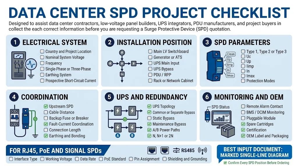
1. Sistema eléctrico
- País y ubicación del proyecto
- Voltaje nominal del sistema
- Frecuencia
- Monofásico o trifásico
- Sistema TN-S, TN-C-S, TT o IT
- Disposición de fase y neutro
- Corriente de cortocircuito prospectiva
2. Posición de instalación
- Entrada de servicio o cuadro principal de BT
- Sección de grupo electrógeno o ATS
- Entrada principal de UPS
- Bypass estático o de mantenimiento
- Panel de salida de SAI
- PDU, RPP o PDU de rack
- Armario de red o de control
3. Parámetros de SPD
- Norma aplicable
- Tipo SPD requerido o clase de prueba
- Uc o MCOV
- Up o VPR
- Iimp, In e Imax cuando sea aplicable
- Modos de protección requeridos
- Dispositivo de protección de respaldo
4. SAI y redundancia
- SAI individual, en paralelo o modular
- Fuente de bypass común o separada
- Disposición del transformador de aislamiento
- Arquitectura N, N+1, 2N u otra
- Diagrama de ruta de alimentación A/B
- Requisito de mantenimiento concurrente
- Procedimiento de aislamiento aceptable
5. Monitorización y mecánica
- Indicación visual de estado
- Contacto remoto NA/NC o de conmutación
- Requisito de supervisión BMS o DCIM
- Construcción enchufable o fija
- Montaje en riel DIN o en panel
- Espacio disponible en el envolvente
- Cantidad necesaria de módulos de repuesto
6. Red y señal
- RJ45, PoE, RS485 u otra interfaz
- Tensión y corriente de funcionamiento
- Velocidad de datos y categoría de transmisión
- Estándar PoE y clase de potencia
- Número y uso de conductores
- Método de blindaje y puesta a tierra
- Tipo de conector y montaje
Lo que las especificaciones débiles de SPD de centro de datos están mal
Especificación débil
- “Proporcione un SPD de 100 kA para el centro de datos.”
- “El SAI ya lo protege todo.”
- “Instale un SPD en el cuadro principal.”
- “Utilice el mismo diseño para las vías de alimentación A y B sin comprobarlas.”
- “Cualquier SPD RJ45 admite todos los sistemas Ethernet y PoE.”
- “Alarma remota significa que el módulo puede reemplazarse en funcionamiento.”
Especificación lista para el proyecto
- Marca todos los puntos de instalación en el diagrama unifilar.
- Indica la tensión del sistema y el esquema de conexión a tierra.
- Especifica la norma aplicable y la clasificación del SPD.
- Incluye la coordinación de la corriente de falta y del dispositivo de protección de reserva.
- Separa la protección de alimentación de CA, red y señal.
- Define los requisitos de supervisión, aislamiento y sustitución.
Evidencia para verificar antes de aprobar un SPD de centro de datos
No apruebe un producto basándose únicamente en la clasificación actual de un catálogo. Confirme el modelo exacto, su documentación y su estrategia de sustitución.
Certificados y alcance
Compruebe que el certificado o informe cubra el modelo exacto solicitado, la tensión, la topología y la clase de protección, y no solo otro producto de la misma familia.
Ver certificados de LEEYEEDocumentación técnica
Revise la hoja de datos, el diagrama de cableado, las dimensiones, la protección de respaldo, la clasificación de los contactos remotos y el código del cartucho de repuesto.
Ver descargas técnicasTrazabilidad exacta del producto
Confirme los números de pieza estables, las etiquetas de producción, los registros de inspección y la disponibilidad a largo plazo de los módulos de repuesto compatibles.
Ver gama de productos SPD- Cumplimiento de normas IEC, EN, UL o locales aplicables al producto.
- Documentación de pruebas para el modelo exacto solicitado.
- Uc y topología correctas para el sistema de puesta a tierra.
- Definiciones claras de Up, Iimp, In e Imax.
- Información sobre cortocircuitos y protección de respaldo.
- Clasificación de contactos remotos y diagrama de cableado.
- Módulos de repuesto compatibles con códigos estables.
- Inspección de producción rutinaria y trazabilidad.
- Etiqueta OEM, embalaje y control de archivo técnico.
- Disponibilidad a largo plazo de módulos de repuesto.
Envíanos tu diagrama unifilar de centro de datos
LEEYEE puede revisar las posiciones propuestas de los SPD para el cuadro general de baja tensión, la entrada del SAI, la ruta de bypass, la PDU, el RPP y los armarios de red. También podemos confirmar las etiquetas OEM, los contactos remotos, los módulos de repuesto y la documentación del proyecto.
Preguntas sobre la protección contra sobretensiones en centros de datos
¿Necesita un centro de datos SPD si ya tiene un SAI de doble conversión?
El SAI no elimina automáticamente la necesidad de protección externa contra sobretensiones. Los componentes de entrada siguen expuestos a tensiones transitorias aguas arriba, y las rutas de bypass y de salida pueden requerir una protección independiente.
¿Deben instalarse los SPDs tanto en la entrada como en la salida del UPS?
La entrada requiere evaluación porque protege los componentes del SAI orientados aguas arriba. La protección de salida es condicional. Considere el aislamiento de salida, la distancia del cable, la distribución aguas abajo, las fuentes de conmutación y la protección existente en la PDU.
¿Se requiere un SPD separado para un bypass de UPS independiente?
Es posible. Una evaluación independiente es especialmente importante cuando el bypass tiene una fuente diferente o no pasa por el mismo punto protegido aguas arriba que la entrada principal del SAI.
¿Qué tipo de SPD se utiliza en el tablero de distribución principal del centro de datos?
El tipo 1 o el combinado tipo 1+2 se utiliza cuando existe riesgo de descarga de rayo. El tipo 2 puede ser adecuado cuando ese requisito no es necesario. Confirme el diseño de la protección contra rayos, la exposición del servicio y la evaluación de riesgos.
¿Cada PDU de centro de datos necesita su propio SPD?
No automáticamente. Revise el SPD aguas arriba, la distancia del conductor, el esquema de distribución, la exposición a conmutaciones, el nivel de resistencia del equipo y cualquier protección ya integrada en la PDU.
¿Puede un SPD proteger tanto las alimentaciones de energía A como B?
Solo cuando ambas alimentaciones comparten realmente el mismo punto protegido y la disposición sigue siendo válida en todas las condiciones normales, de bypass y de mantenimiento. La mayoría de las rutas redundantes deben documentarse por separado.
¿Necesitan las líneas de fibra óptica un protector contra sobretensiones RJ45?
Una ruta de fibra totalmente dieléctrica no conduce corrientes de sobretensión como el Ethernet de cobre. Los convertidores de medios alimentados, los elementos metálicos de los cables, las fuentes de alimentación y el cableado de control de cobre en paralelo siguen requiriendo una revisión.
¿Con qué frecuencia deben reemplazarse los módulos SPD del centro de datos?
No existe un período de sustitución de calendario universal. Supervise el estado del SPD, siga las instrucciones del fabricante, inspeccione después de eventos eléctricos importantes y sustituya los módulos fallidos por el cartucho compatible exacto.
¿Qué información debe incluirse en una solicitud de cotización SPD para un centro de datos?
Incluya el diagrama unifilar, el punto de instalación, la tensión, la frecuencia, el sistema de puesta a tierra, la corriente de cortocircuito, la norma aplicable, el tipo de SPD, Uc o MCOV, Up o VPR, los valores nominales de descarga, la protección de reserva, la topología del SAI, el contacto remoto y el espacio del armario.
Fuentes y normas
- IEC 61643-11:2025, Dispositivos de protección contra sobretensiones de baja tensión – Dispositivos de protección contra sobretensiones conectados a sistemas de alimentación de baja tensión de CA – Requisitos y métodos de ensayo. Tienda virtual de la IEC
- IEC 61643-12:2020, Dispositivos de protección contra sobretensiones de baja tensión – Principios de selección y aplicación para SPD conectados a sistemas de alimentación de baja tensión. Tienda virtual de la IEC
- IEC 62305-4:2024, Protección contra el rayo – Sistemas eléctricos y electrónicos en estructuras. Tienda virtual de la IEC
- IEC 61643-21:2025, SPD conectados a redes de telecomunicaciones y señalización – Requisitos y métodos de ensayo. Tienda virtual de la IEC
- IEC 61643-22:2015, SPD para redes de telecomunicaciones y señalización – Principios de selección y aplicación. Tienda virtual de la IEC
- IEC 61643-01:2024, Dispositivos de protección contra sobretensiones de baja tensión – Requisitos generales y métodos de ensayo. Tienda virtual de la IEC
- Uptime Institute, principios de clasificación Tier y certificación Tier para infraestructuras de centros de datos con mantenibilidad concurrente y tolerancia a fallos. Uptime Institute
- UL Solutions, servicios de ensayo y certificación de dispositivos de protección contra sobretensiones, incluyendo la evaluación según UL 1449. Soluciones UL
