
Un SPD de espacio de chispa N-PE es la ruta de protección contra sobretensiones dedicada instalada entre el neutro y tierra protectora en muchas disposiciones 3+1 y 1+1. También puede describirse como un pararrayos N-PE, pararrayos de corriente de rayo N-PE o módulo de protección de espacio de chispa N-PE.
Para los fabricantes de paneles y compradores de OEM, la cuestión importante no es solo qué es el componente. Necesita saber por qué se utiliza en sistemas TT, cómo se diferencia de un módulo MOV ordinario y qué datos específicos de la ruta deben verificarse antes de aprobar el SPD completo.
Índice
Respuesta rápida: ¿Qué es un SPD de espacio de chispa N-PE?
Un N-PE SPD de chispa es un elemento de conmutación de voltaje conectado entre el neutro y la tierra de protección. Durante el funcionamiento normal, permanece en un estado de alta impedancia. Durante un pico, cambia a conducción y proporciona un camino de descarga de N a PE.
En un SPD típico de tres fases 3+1, tres caminos limitadores de voltaje protegen L1-N, L2-N y L3-N. El cuarto camino protege N-PE. Los pararrayos basados en chispa N-PE se utilizan en configuraciones documentadas de 3+1 y 1+1 para sistemas TT y TN seleccionados, según el diseño de instalación e instrucciones del fabricante.[3][5]
| Ruta de protección | Función típica | Verificaciones principales del comprador |
|---|---|---|
| L1-N, L2-N, L3-N | Limitar el voltaje de sobretensión fase-a-neutro | Uc, Up, In, Imax o Iimp |
| N-PE | Proporcionar el camino de descarga común de neutro a tierra | Uc, Up, TOV, corriente de seguimiento, In o Iimp |
Significado del comprador: nunca aprobar un “SPD 4P” solo por el número de polos. Confirmar si el circuito interno es 3+1 o 4+0 y verificar el camino N-PE por separado.
¿Qué significa la protección N-PE?
N significa neutro. PE significa tierra de protección. La protección N-PE significa que el SPD incluye un camino de protección contra sobretensiones definido entre estos dos conductores.
El camino N-PE no está destinado a transportar la corriente de carga normal. Su propósito es controlar el voltaje excesivo entre el neutro y la tierra durante un evento transitorio.
En un arreglo de 3+1, la corriente de sobretensión de los conductores de fase es manejada primero por los tres caminos L-N. El elemento N-PE luego proporciona la ruta de descarga compartida hacia la tierra de protección.
¿Por qué son comunes los SPDs 3+1 en sistemas TT?
En un sistema TT, la tierra de protección de la instalación se conecta a una disposición de puesta a tierra local. El neutro está conectado al punto de puesta a tierra de la fuente. N y PE permanecen separados dentro de la instalación.
Una disposición 3+1 permite que los tres caminos de protección de fase a neutro funcionen juntos con un camino dedicado de neutro a tierra. La IEC 61643-12 proporciona principios para seleccionar, ubicar y coordinar SPDs de CA, mientras que la IEC 60364-5-53 cubre la selección y la instalación de dispositivos utilizados en instalaciones de baja tensión.[3][4]
La documentación oficial del fabricante también identifica supresores N-PE basados en salto de chispa para disposiciones 3+1 y 1+1 en sistemas TT y, dependiendo del producto y diseño, sistemas TN seleccionados.[5]
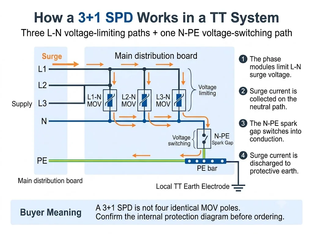
Para una explicación a nivel de sistema más amplia, consulte el. Guía del sistema SPD TT. Esta página se centra en el módulo de salto de chispa N-PE y su significado de procuración.
3+1 vs 4+0: ¿Qué cambios hay dentro del SPD?
Ambas configuraciones pueden venderse en carcasas que parecen tener cuatro polos. La diferencia importante es la topología de protección interna.
La columna más importante es "Vías de protección". Muestra por qué el número de polos por sí solo no es suficiente.
| Disposición | Rutas de protección | Función N-PE | El comprador debe confirmar |
|---|---|---|---|
| 3+1 | L1-N, L2-N, L3-N más N-PE | Ruta de descarga final compartida de neutro a tierra | Tecnología N-PE, valores nominales y datos de ensamblaje total |
| 4+0 | L1-PE, L2-PE, L3-PE y N-PE, u otra disposición declarada de conductor a tierra (PE) | Uno de los cuatro caminos de conductor a tierra (PE) en lugar del camino común "+1" | Circuito exacto, tecnología y adecuación al sistema de puesta a tierra |
Conclusión de adquisición: "3P+N", "4P", "3+1" y "4+0" no siempre se utilizan de forma coherente en todos los mercados. Solicite el diagrama de circuito interno.
La comparación detallada de configuraciones completas de cuatro polos pertenece a la Guía de SPD 3P+N vs 4P. Para esta página, el punto clave es que un SPD 3+1 otorga al módulo N-PE un papel específico de descarga compartida.
¿Qué hace el espacio de chispa en el camino N-PE?
Un descargador de gas es un elemento de protección de conmutación de tensión. Permanece altamente aislante durante el funcionamiento normal. Cuando se alcanza su condición de conmutación durante una sobretensión, cambia rápidamente a un estado conductor.
Una vez pasada la sobretensión, un SPD basado en descargador de gas de CA también puede necesitar extinguir la corriente suministrada por el sistema eléctrico. Las normas IEC 61643-01 e IEC 61643-11 incluyen requisitos relativos a los SPD y modos de protección con corriente de seguimiento.[1][2]
En la selección práctica de N-PE, tres características merecen una atención especial:
- Alto aislamiento entre neutro y tierra durante el funcionamiento normal
- Capacidad de corriente de sobretensión declarada durante el funcionamiento
- Comportamiento ante TOV y corriente de seguimiento en condiciones de CA anormales
Espacio de chispa N-PE vs módulo MOV ordinario
Un descargador de gas N-PE y un módulo MOV no deben compararse como si fueran componentes intercambiables. Utilizan principios de funcionamiento diferentes y normalmente protegen rutas distintas dentro de la configuración 3+1.
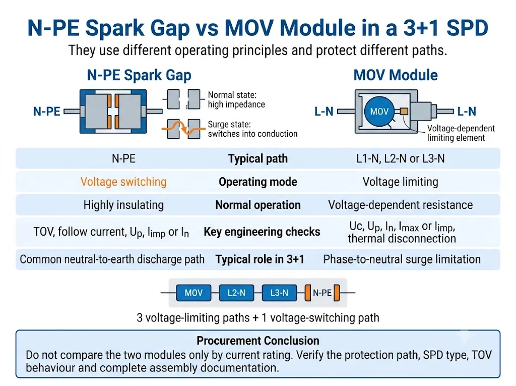
Compare primero la función de protección. La intensidad nominal por sí sola no indica si dos módulos realizan la misma función.
| Punto de decisión | Espacio de chispa N-PE | Módulo MOV |
|---|---|---|
| Principio de funcionamiento | Conmutación de tensión | Limitación de tensión |
| Ruta 3+1 típica | N-PE | L1-N, L2-N or L3-N |
| Estado normal | Altamente aislante antes de la descarga | Resistencia dependiente de la tensión |
| Comprobaciones clave de CA | Comportamiento ante TOV y corriente de seguimiento | Estabilidad térmica y desconexión |
| Calificaciones clave | Uc, Up, In o Iimp, corriente total donde se declare | Uc, Up, In, Imax o Iimp |
Conclusión de adquisición: ninguna tecnología es universalmente mejor. La idoneidad depende de la ruta de protección, la clasificación del SPD y el rendimiento declarado del conjunto completo.
Para una comparación más amplia de ambas tecnologías operativas, consulte la Guía de descargadores de gas (Spark Gap) frente a MOV SPD.
¿Es siempre un espacio de chispa N-PE un SPD de tipo 1?
No. La tecnología de descargador de gas no convierte automáticamente al SPD completo en un dispositivo de Tipo 1.
La documentación oficial del producto muestra tanto descargadores de sobretensiones por rayo N-PE de Tipo 1 como dispositivos de descargador de gas N-PE de Tipo 2. La clasificación debe confirmarse a partir de la declaración y la documentación de prueba del SPD completo o del modo de protección declarado.[2][5][6]
La diferencia clave es la clasificación de prueba declarada, no el aspecto visual del cartucho N-PE.
| Artículo | Ruta N-PE de Tipo 1 | Ruta N-PE de Tipo 2 |
|---|---|---|
| Prueba de impulso principal | Iimp con forma de onda de corriente de 10/350 µs | In y, habitualmente, Imax con forma de onda de corriente de 8/20 µs |
| Rol típico en el proyecto | Gestión de corriente de rayo en una posición de entrada relevante | Limitación de sobretensiones y protección aguas abajo coordinada |
| Tecnología | Puede utilizar un explosor | También puede utilizar un explosor |
| Evidencia de homologación | Declaración completa de Tipo 1 o Tipo 1+2 | Declaración completa de Tipo 2 |
Aviso al comprador: no deduzca el rendimiento de Tipo 1 únicamente a partir de las palabras «explosor», «N-PE» o «protección contra rayos».
¿Cómo afecta el módulo N-PE a la coordinación RCD?
Las instalaciones TT utilizan habitualmente dispositivos de corriente residual como parte del esquema de protección contra fallos. Por tanto, la posición del SPD y la disposición del RCD deben revisarse conjuntamente.
Una trayectoria N-PE basada en explosor proporciona normalmente un aislamiento muy elevado durante el funcionamiento ordinario. Esto puede ayudar a evitar una trayectoria neutro-tierra continuamente conductora o sometida a tensión continua.
Sin embargo, la corriente de descarga que pasa a través de un SPD aún puede afectar a un RCD. El resultado depende de la posición de los dispositivos, las características del RCD, el sistema de puesta a tierra, los modos de protección del SPD y la disposición de la instalación. La norma IEC 61643-12 aborda la selección, ubicación y coordinación de los SPD, mientras que la norma IEC 60364-5-53 proporciona el marco de instalación que debe aplicarse al proyecto concreto.[3][4]
Los detalles de la instalación, la longitud de la conexión, la protección de respaldo y la relación con el RCD se tratan más detalladamente en el Guía de instalación de SPD según IEC 60364-5-534.
¿Qué parámetros N-PE deben verificar los compradores?
1. Modo de protección declarado
La hoja de datos o el diagrama de circuito deben identificar claramente la trayectoria N-PE. No deduzca el modo de protección a partir del color del cartucho o de su posición en la carcasa.
2. Tensión máxima de funcionamiento continuo, Uc
Confirme la Uc declarada para la trayectoria N-PE. Es posible que no sea el mismo valor utilizado para los módulos de fase L-N.
3. Nivel de protección de tensión, Up
Compruebe la Up declarada para N-PE, así como el nivel de protección del modo completo o del conjunto. Las normas IEC 61643-01 e IEC 61643-11 distinguen el ensayo de SPD completos, modos de protección y conjuntos de SPD.[1][2]
4. Iimp, In e Imax
Para un rendimiento de Tipo 1, verifique la Iimp utilizando la forma de onda 10/350 µs. Para un rendimiento de Tipo 2, verifique la In y, cuando se declare, la Imax utilizando la forma de onda 8/20 µs.
5. Capacidad de descarga total
Algunos productos 3+1 declaran la corriente total para el conjunto completo o la trayectoria N-PE compartida. No confunda este valor con la capacidad nominal de un cartucho L-N.
6. Comportamiento ante sobretensiones temporales (TOV)
La TOV es una sobretensión a frecuencia industrial que dura mucho más que un impulso de sobretensión. Confirme si el producto resiste la condición declarada o si entra en un modo de fallo seguro definido. Los datos de TOV específicos del producto deben obtenerse de la documentación del modelo exacto.[7][8]
7. Capacidad de extinción de la corriente de seguimiento
Cuando la corriente de seguimiento sea relevante y esté declarada, confirme la capacidad de extinción del explosor N-PE. No suponga que todos los diseños de explosores tienen el mismo comportamiento.[2][8]
8. Protección de respaldo y datos de cortocircuito
Confirme el fusible o disyuntor aguas arriba requerido y la capacidad de cortocircuito del SPD completo. No seleccione la protección de respaldo a partir del valor de un único cartucho.
9. Sustitución, indicación de estado y señalización remota
Compruebe si el elemento N-PE es sustituible, si dispone de indicación visual de estado y si el contacto remoto supervisa el conjunto completo.
¿Cómo verificar un SPD 3+1 antes de la aprobación de OEM o proyecto?
El proceso de compra más seguro consiste en confirmar primero el sistema, después la disposición de protección interna y solo entonces aprobar las características eléctricas y el modelo físico.
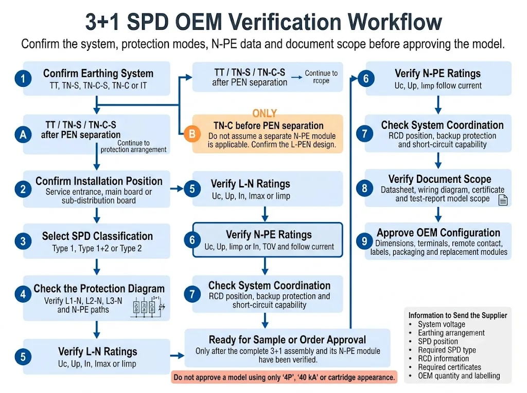
- Confirme el sistema de puesta a tierra. Identifique si la instalación es TT, TN-S, TN-C-S, TN-C o IT. Para TN-C-S, indique si el SPD se instala antes o después de la separación del PEN.
- Confirme la posición de instalación. Indique si el SPD se encuentra en la acometida, en el cuadro general de distribución o en un cuadro de distribución secundario.
- Seleccione la clasificación de SPD requerida. Confirme si el proyecto requiere un rendimiento de Tipo 1, Tipo 1+2 o Tipo 2.
- Verifique el circuito interno. Confirme si es 1+1, 3+1, 4+0 u otra disposición declarada según el esquema de conexión.
- Compruebe las vías L-N y N-PE por separado. Verifique Uc, Up y los valores nominales de corriente de descarga aplicables para cada parte.
- Revise el comportamiento ante TOV y corriente de seguimiento. Utilice la hoja de datos exacta del modelo. No sustituya valores de un producto de aspecto similar.
- Compruebe la coordinación del sistema. Confirme la posición del RCD, la protección de respaldo y los requisitos de cortocircuito.
- Verifique el alcance del documento. Confirme que la hoja de datos, el certificado, el informe de pruebas y las instrucciones de instalación cubren el conjunto completo real.
- Apruebe la configuración OEM. Confirme dimensiones, terminales, contacto remoto, codificación de cartuchos, etiquetas, embalaje y referencias de sustitución.
¿Qué evidencia debería respaldar la aprobación del proyecto?
Los gráficos técnicos explican el circuito, pero la aprobación del proyecto debe basarse en pruebas específicas del modelo. Los compradores deben solicitar documentos que identifiquen el conjunto exacto y su módulo N-PE.
Muestra si el producto completo es 3+1, 4+0 u otra disposición de protección.
Enumera los valores nominales L-N y N-PE, los datos de TOV, el nivel de protección y los requisitos de respaldo.
Confirma qué modelo, configuración y edición de la norma están realmente cubiertos.
Define los terminales aprobados, la disposición de los conductores, la protección de respaldo y el proceso de sustitución.
Las recomendaciones de modelos de LEEYEE deben confirmarse con la hoja de datos, el plano y los documentos de conformidad específicos del modelo actual antes del muestreo o la aprobación del pedido. CNSPD es la plataforma de LEEYEE centrada en protección contra sobretensiones para compradores técnicos globales.
Errores comunes al solicitar un SPD N-PE o 3+1
Realizar pedidos solo por "4P"
Cuatro módulos visibles no prueban que el producto utilice un circuito 3+1.
Tratar los cuatro módulos como idénticos
La vía de chispas N-PE puede utilizar una tecnología y unos parámetros diferentes a los de los tres módulos L-N.
Suponer que todas las vías de chispas son de Tipo 1
También existen productos con vía de chispas N-PE de Tipo 2. Confirme la clasificación completa del SPD.[6]
Comparar solo la Imax
La Imax por sí sola no explica la capacidad de Tipo 1, el comportamiento ante sobretensiones temporales (TOV), la corriente de seguimiento, el nivel de protección de tensión o el rendimiento del conjunto completo 3+1.
Ignorar la posición del RCD
Un mismo SPD puede interactuar de forma diferente con la instalación según el tipo de RCD, su ubicación y la disposición del cableado.
Sustituir un cartucho por su apariencia
Carcasas similares pueden tener valores Uc, codificación, modos de protección o compatibilidad de base diferentes.
Comprobar los documentos de un solo módulo
La hoja de datos de un cartucho no demuestra automáticamente que el conjunto 3+1 completo cuente con el alcance de prueba o certificado requerido.
Antes de ordenar, prepara estos detalles
- Tensión y frecuencia nominales del sistema
- Sistema TT, TN-S, TN-C-S, TN-C o IT
- Posición de instalación del SPD
- Clasificación requerida de Tipo 1, Tipo 1+2 o Tipo 2
- Disposición requerida 1+1, 3+1, 4+0 u otra
- Valores Uc L-N y N-PE
- Valores Up L-N y N-PE
- Iimp, In, Imax o corriente total requerida
- Comportamiento TOV N-PE
- Requisito de corriente de seguimiento cuando sea aplicable
- Información sobre el fusible de respaldo o el disyuntor
- Tipo de RCD y posición de instalación
- Requisito de señalización remota
- Ancho de carril DIN y disposición de los terminales
- Estándar requerido y alcance del certificado
- Etiqueta OEM, embalaje, cantidad y módulos de repuesto
Confirma una configuración de SPD N-PE o 3+1
Envíe la tensión del sistema, la disposición de puesta a tierra, la posición de instalación, el tipo de SPD requerido, la información del RCD, el diagrama de protección y los requisitos de corriente de descarga.
LEEYEE puede utilizar estos detalles para revisar la configuración solicitada y preparar una recomendación de modelo para cuadros de distribución, suministro de proyectos u homologación OEM. La selección final queda sujeta al diseño del proyecto, las normas aplicables y la documentación específica del modelo.
Confirmar una configuración de SPD OEMPreguntas frecuentes sobre los SPDs de espacio de chispa N-PE
¿Qué significa N-PE en un SPD?
N-PE identifica una trayectoria de protección contra sobretensiones entre el neutro y la tierra de protección. En muchos productos 3+1, esta trayectoria utiliza una vía de chispas de conmutación de tensión.
¿Por qué se utiliza una vía de chispas N-PE en un SPD 3+1?
La ruta N-PE realiza una función diferente a la de las tres rutas L-N. Proporciona la ruta de descarga compartida de neutro a tierra, manteniéndose altamente aislante durante el funcionamiento normal.
¿Es un SPD 3+1 lo mismo que cualquier SPD de cuatro polos?
No. Un producto de cuatro polos puede utilizar una configuración 3+1, 4+0 u otra configuración declarada. Se requiere el diagrama del circuito interno.
¿Es cada descargador de gas (vía de chispas) N-PE un dispositivo de Tipo 1?
No. La documentación oficial del producto muestra tanto descargadores de sobretensiones de corriente de rayo N-PE de Tipo 1 como dispositivos de vía de chispas N-PE de Tipo 2.[5][6]
¿Puede un módulo MOV reemplazar a un cartucho de vía de chispas N-PE?
No sin aprobación técnica. El principio de funcionamiento, el modo de protección, el comportamiento frente a tensiones temporales (TOV), el comportamiento frente a corrientes de seguimiento y la coordinación completa del conjunto pueden ser diferentes.
¿Evita una vía de chispas N-PE los disparos intempestivos del interruptor diferencial (RCD)?
Puede proporcionar un alto aislamiento durante el funcionamiento normal, pero no puede garantizar que un RCD nunca se dispare. La coordinación depende de la posición del SPD, las características del RCD y la disposición de la instalación.
¿Debería el módulo N-PE tener la misma capacidad nominal de corriente que los módulos de fase?
No automáticamente. La ruta compartida N-PE puede declararse utilizando datos de corriente total o específicos de la ruta diferentes. Utilice la documentación completa del conjunto.
¿Qué documentos debe solicitar un comprador OEM?
Solicite el diagrama del circuito, la hoja de datos específica del modelo, las instrucciones de instalación, la información sobre la protección de respaldo, el alcance del certificado o informe de prueba, el plano dimensional y las referencias de los módulos de repuesto.
Referencias
- Comisión Electrotécnica Internacional, IEC 61643-01:2024, Dispositivos de protección contra sobretensiones de baja tensión — Parte 01: Requisitos generales y métodos de ensayo. Página de publicación oficial de la IEC.
- Comisión Electrotécnica Internacional, IEC 61643-11:2025, Dispositivos de protección contra sobretensiones de baja tensión — Parte 11: Dispositivos de protección contra sobretensiones conectados a sistemas de potencia de baja tensión de CA — Requisitos y métodos de ensayo. Página de publicación oficial de la IEC.
- Comisión Electrotécnica Internacional, IEC 61643-12:2020, Dispositivos de protección contra sobretensiones de baja tensión — Parte 12: Dispositivos de protección contra sobretensiones conectados a sistemas de potencia de baja tensión — Principios de selección y aplicación. Página de publicación oficial de la IEC.
- Comisión Electrotécnica Internacional, IEC 60364-5-53:2019+AMD1:2020+AMD2:2024 CSV, Instalaciones eléctricas de baja tensión — Parte 5-53: Selección e instalación de equipos eléctricos — Dispositivos para protección para la seguridad, aislamiento, seccionamiento, control y vigilancia. Página de publicación oficial de la IEC.
- DEHN, Descargadores de corriente de rayo N-PE, información oficial de aplicación y categoría de producto para descargadores N-PE de Tipo 1 basados en vía de chispas utilizados en configuraciones 3+1 y 1+1. Página oficial de DEHN.
- Phoenix Contact, VAL-ME-N/PE — Dispositivo de protección contra sobretensiones de Tipo 2, información oficial del producto que identifica un descargador de Tipo 2 como una vía de chispas N-PE. Página oficial de Phoenix Contact.
- OBO Bettermann, Protector contra sobretensiones V20, libre de corriente de fuga, 3 polos + NPE, datos oficiales del producto y de TOV específicos del modelo. Página oficial de OBO.
- OBO Bettermann, Protector contra sobretensiones V20 con fusible previo integrado, 3+NPE, datos oficiales de TOV, protección de respaldo y corriente de seguimiento N-PE específicos del modelo. Página oficial de OBO.
