
Um SPD pode sobreviver a um impulso de raios muito alto, mas falhar durante uma tensão muito mais baixa que permanece por segundos ou mais. Essa tensão anormal mais longa é chamada de sobrevoltagem temporária, ou TOV.
Para compradores de OEM e construtores de painéis, a resistência TOV é um parâmetro de risco de aquisição. Ela ajuda a determinar se um SPD pode permanecer estável, desconectar de maneira controlada ou sofrer danos sérios quando a tensão do sistema ultrapassa sua faixa de operação contínua pretendida.
Índice
O que é a resistência TOV de SPD?
Uma sobretensão é um evento transitório curto que um SPD é projetado para limitar. Um TOV é uma tensão anormal de frequência de potência ou DC que permanece tempo suficiente para criar estresse elétrico e térmico sustentado.[1][2][4]
A resistência a TOV não é um número de tensão isolado. Uma declaração significativa deve identificar o modo de proteção, a tensão aplicada, a duração e o resultado esperado.
- Uc ou Ucpv cobre a tensão contínua. A tensão real de operação deve permanecer dentro da classificação declarada.
- UT descreve uma condição anormal definida. Deve ser lido juntamente com a duração e o resultado do teste.
- Baixo Uc pode aumentar a sensibilidade ao TOV. Condução sustentada de MOV pode causar aquecimento e desconexão.
- Alto Imax não prova a resistência a TOV. Os riscos de corrente de impulso e tensão sustentada são diferentes.
Decisão rápida de aprovação para compradores
Use esta tabela antes de aprovar uma amostra, item de BOM ou modelo de marca privada. É uma ferramenta de triagem, não um substituto para engenharia de projeto.
| Decisão | Constatação | Ação necessária |
|---|---|---|
| Aprovar | Os dados do modelo exato correspondem à tensão do sistema, modo de proteção, condição de TOV e requisitos de curto-circuito. | Prossiga para a aprovação de amostra ou BOM, sujeita à revisão completa do projeto. |
| Aguarde | A UT é apresentada sem duração, o resultado de falha segura é incerto, ou o escopo do certificado não identifica o modelo exato. | Solicite a condição de teste ausente, escopo do relatório e informações de instalação. |
| Rejeitar | A tensão máxima normal excede Uc ou Ucpv, o tipo de aplicação está incorreto, ou o modo de proteção necessário não é suportado. | Selecione outro modelo ou corrija a especificação do sistema antes de fazer o pedido. |
Um produto não deve ser aprovado apenas com base em um rótulo frontal, valor de Imax ou declaração genérica de “resistente a TOV”.
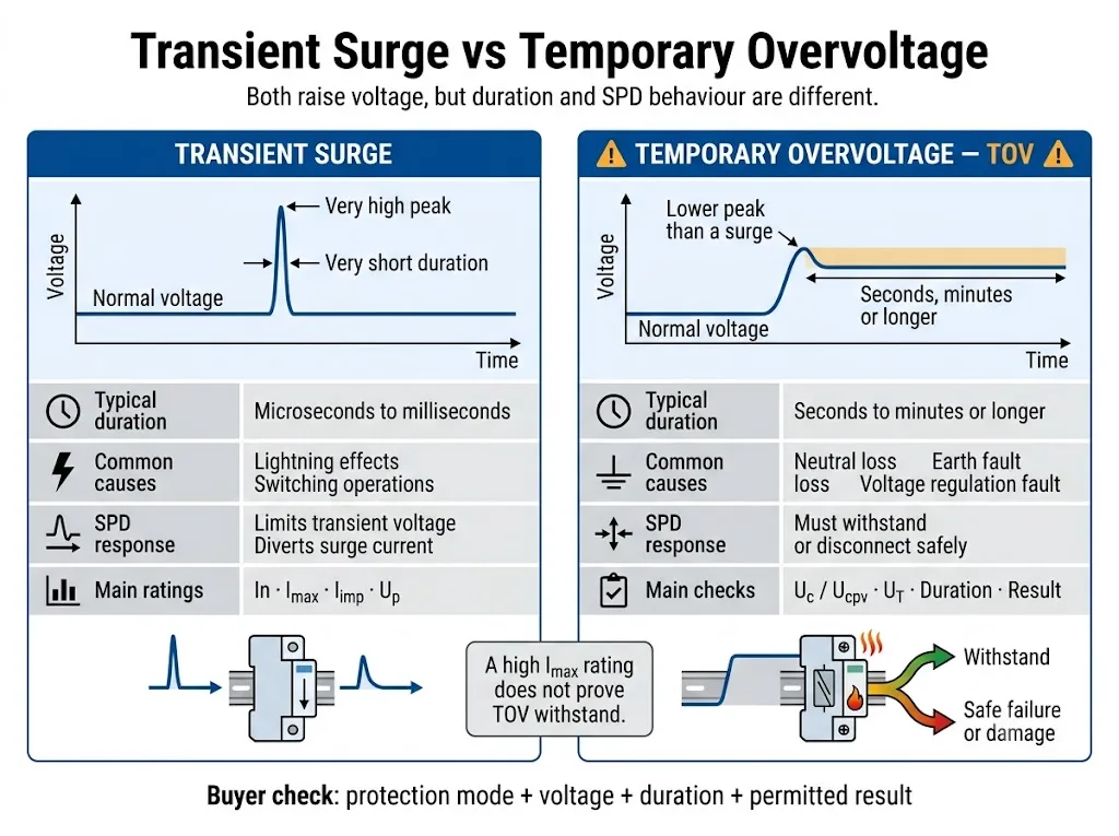
TOV e surto são eventos elétricos diferentes
Ambos os eventos elevam a tensão acima do seu nível normal. As diferenças importantes são a duração, a fonte de energia e a forma como o SPD responde.
| Comparação | Sobretensão transitória | Sobretensão temporária |
|---|---|---|
| Natureza | Um impulso curto de tensão ou corrente com um pico elevado. | Uma tensão AC RMS ou DC anormal que permanece presente. |
| Causas possíveis | Efeitos de relâmpagos, comutação e interrupção de carga indutiva. | Perda de neutro, faltas à terra, regulação deficiente, tensão de alimentação incorreta ou faltas na fonte. |
| Função do SPD | Limita a tensão transitória e desvia a corrente de impulso. | Deve permanecer estável ou entrar na condição de fim de vida útil controlada declarada. |
| Classificações principais | In, Imax, Iimp e Up. | Uc ou Ucpv, UT, modo de proteção, duração e resultado. |
| Principal risco | Energia de impulso excessiva ou stress de sobretensão acumulado. | Condução contínua, aquecimento, embalamento térmico ou continuação da corrente de falha. |
A norma aplicável e a documentação do produto determinam a duração exata do ensaio TOV. Não aplique um limite de tempo universal a todos os sistemas ou SPD.
Quatro campos são necessários para entender uma classificação TOV
Declarações como "elevada resistência a TOV" ou "SPD à prova de TOV" não são dados de engenharia completos. Os compradores necessitam de quatro campos específicos.
| Campo obrigatório | O que isso significa | Impacto na aquisição |
|---|---|---|
| Modo de proteção | Os dois condutores entre os quais é aplicada a tensão anormal. | Os caminhos L-N, L-PE e N-PE podem sofrer diferentes tensões de falha. |
| Tensão aplicada | A tensão de ensaio TOV especificada em AC RMS ou DC, frequentemente identificada como UT. | Compare-a com a tensão anormal credível no sistema real. |
| Duração | Quanto tempo a tensão anormal é aplicada durante a condição declarada. | Um SPD pode resistir a uma tensão brevemente, mas desligar-se durante uma exposição mais longa. |
| Resultado | O comportamento exigido após ou durante o ensaio. | Determine se o SPD permanece funcional, se se desliga ou se requer substituição. |
Uc, Ucpv e UT não significam a mesma coisa
Uc é a tensão de funcionamento contínua máxima que pode ser aplicada continuamente ao modo de proteção SPD declarado. Ucpv é o parâmetro correspondente utilizado para SPD fotovoltaicos.[1][2][6]
UT descreve o comportamento durante uma condição específica de tensão anormal temporária. Uc ou Ucpv e UT estão relacionados, mas um não pode substituir o outro.
| Parâmetro | Questão respondida | Risco de aprovação |
|---|---|---|
| Un ou Uo | Qual é a tensão nominal do sistema ou fase-neutro? | É um ponto de partida, não o valor final de seleção da tensão do SPD. |
| Uc | O SPD pode permanecer ligado continuamente a esta tensão? | Um valor demasiado baixo pode aumentar a corrente de fuga, o aquecimento e o desligamento prematuro. |
| Ucpv | O SPD fotovoltaico pode permanecer ligado à tensão máxima calculada do array? | A tensão de funcionamento normal do inversor, por si só, não é suficiente. |
| UT | O que acontece sob a tensão anormal e a duração declaradas? | Um valor de tensão sem duração e resultado está incompleto. |
| Para cima | Que nível de proteção de tensão é declarado durante o ensaio de sobretensão especificado? | Um Uc mais elevado não fornece automaticamente a coordenação de proteção mais adequada. |
Porque pode um Uc baixo causar falhas?
A maioria dos SPD de potência AC limitadores de tensão utiliza um ou mais varistores de óxido metálico (MOV). Sob tensão normal, um MOV transporta apenas uma pequena corrente de fuga.
Quando a tensão aplicada aumenta para além da gama de funcionamento estável do componente, a corrente do MOV pode aumentar drasticamente. Se a tensão anormal persistir, a energia elétrica é convertida em calor em vez de ser tratada como um curto impulso de sobretensão.[9]
É um Uc mais elevado sempre melhor?
Não. Um Uc mais elevado pode aumentar a margem de tensão contínua, mas o SPD selecionado deve ainda fornecer um Up adequado, um modo de proteção e coordenação com o equipamento que está a ser protegido.
A escolha correta não é simplesmente o Uc mais elevado disponível. É uma classificação que cobre de forma segura a tensão máxima de funcionamento real e as condições de falha credíveis, cumprindo simultaneamente o nível de proteção exigido.[3]
Como o TOV pode fazer um SPD aquecer, desconectar ou queimar?
A resposta exata depende da tecnologia do SPD, da construção interna e da falha do sistema. Uma sequência comum de falha baseada em MOV é apresentada abaixo.
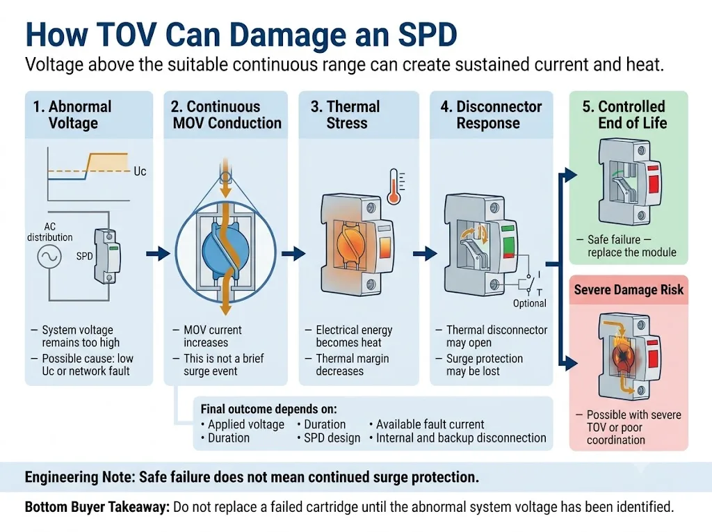
- A tensão aplicada excede a gama contínua adequada. Isto pode resultar de uma seleção de Uc baixa ou de uma condição anormal do sistema.
- O componente limitador de tensão conduz continuamente. O SPD está a consumir corrente de frequência industrial ou CC em vez de processar um curto impulso.
- A temperatura interna aumenta. A entrada contínua de energia reduz a margem térmica restante.
- O seccionador térmico pode abrir. Uma desconexão controlada pode isolar o componente sob tensão e alterar o indicador de estado.
- Danos graves continuam a ser possíveis. Uma TOV severa, uma corrente de falha disponível elevada ou uma desconexão inadequada podem aumentar a falha.
A investigação sobre TOV realizada pelo NIST constatou que as respostas dos SPD sob tensão anormal sustentada podem variar entre a ausência de danos e a destruição total. O documento identifica a tensão de funcionamento contínuo máxima e a resposta do seccionador como fatores importantes na suscetibilidade à TOV.[9]
O TOV deve ser verificado para cada modo de proteção
Um SPD multipolar não está exposto a uma única tensão. Cada elemento de proteção observa a tensão entre os dois condutores ligados a esse caminho de proteção.
| Modo de proteção | Pergunta de seleção normal | Risco de TOV a confirmar |
|---|---|---|
| L-N | Qual é a tensão máxima de funcionamento contínuo fase-neutro? | Perda de neutro, ligação deficiente ao neutro e desequilíbrio de carga. |
| L-PE | Que tensão pode surgir entre o condutor de fase e a terra? | Falhas à terra, deslocamento do neutro e comportamento do sistema de ligação à terra. |
| N-PE | Que tecnologia e classificação de proteção N-PE são utilizadas? | Tensão temporária neutro-terra durante certas condições de falha à terra. |
| CC +/− | Qual é a tensão CC máxima polo-a-polo? | Tensão de carregamento, falhas de regulação e configuração incorreta do circuito. |
| Polo CC-PE | Como é que o sistema CC é referenciado à terra? | Uma falha à terra pode deslocar a tensão através de um caminho de proteção polo-a-terra. |
Por que a perda de neutro é um cenário crítico de TOV em CA?
Num sistema trifásico de quatro fios de 230/400 V em bom estado, um caminho de proteção L-N observa normalmente cerca de 230 V.
Se o condutor neutro abrir ou desenvolver uma impedância elevada, o ponto neutro deixa de ser estável. Com cargas monofásicas desequilibradas, algumas tensões L-N podem baixar enquanto outra sobe substancialmente e pode aproximar-se da tensão entre fases de 400 V.[4][9]
Fornecimento normal versus condição de perda de neutro
Um SPD de 275 V Uc pode ser adequado para um circuito L-N estável de 230 V quando os requisitos completos do sistema e do produto são cumpridos.
Se a perda de neutro fizer com que o mesmo caminho de proteção sofra uma tensão sustentada muito mais elevada, o SPD pode começar a conduzir continuamente. Se resiste, se se desliga em segurança ou se sofre danos, deve ser confirmado a partir dos dados de TOV do modelo exato.
Este exemplo não prova que todos os eventos de perda de neutro produzem exatamente 400 V. A tensão real depende das cargas ligadas, da disposição da rede e da condição de falha.
Falhas à terra e disposição de ligação à terra
Os sistemas TN-S, TN-C-S, TT e IT podem colocar diferentes tensões temporárias através dos caminhos de proteção L-N, L-PE e N-PE. O esforço real depende da disposição da instalação e da condição de falha.[3][4]
Isto é especialmente importante ao comparar circuitos 4+0 e 3+1. Os módulos L-N e o elemento N-PE desempenham funções diferentes e não deve presumir-se que tenham um comportamento de TOV idêntico.
Geradores, transformadores e redes instáveis
Falhas de regulação de geradores, erros de derivação de transformadores, rejeição de carga, ferro-ressonância e regulação deficiente da rede elétrica podem criar tensão anormal sustentada.
Para estes projetos, solicite registos de medição de tensão ou a tolerância de tensão de projeto. A tensão nominal por si só não é suficiente para a aprovação final de Uc.
Os requisitos ao nível da instalação e as condições de TOV específicas do sistema devem ser verificados de acordo com a edição aplicável da IEC 60364 e com a regulamentação elétrica local. O relacionado Guia de instalação de DPS conforme a norma IEC 60364-5-534 explica as verificações de instalação mais abrangentes.
Como ler uma entrada de ficha técnica real de TOV
O exemplo seguinte utiliza valores publicados num guia técnico de um fabricante terceiro. Explica apenas o método de leitura. Não é uma recomendação para um modelo LEEYEE e não deve ser transferido para outro produto sem verificação.[10]
| Entrada publicada | Interpretação correta | Assunção errada a evitar |
|---|---|---|
| Uc 275 V | A tensão de funcionamento contínuo máxima declarada para o modo de proteção indicado. | O produto pode funcionar continuamente a qualquer tensão abaixo do seu valor UT mais elevado. |
| UT 337 V / 5 s | Uma condição de TOV de curta duração com o resultado indicado na mesma documentação do produto. | 337 V é outra classificação de tensão de funcionamento contínuo. |
| UT 442 V / 120 min | Uma condição de duração mais longa associada a um resultado declarado de falha segura. | O SPD continua a proteger normalmente durante duas horas a 442 V. |
| Valor N-PE separado | Uma condição de TOV especificamente declarada para o elemento de proteção N-PE. | O mesmo valor aplica-se automaticamente aos elementos L-N e L-PE. |
O que deve ser verificado num modelo LEEYEE?
Não presuma que um exemplo de terceiros representa um produto LEEYEE. Solicite a ficha técnica exata do modelo LEEYEE, o esquema de ligação e o âmbito do teste ou certificado aplicável para confirmação do projeto.
Evidência específica do modelo a solicitar
- Etiqueta exata do produto e do cartucho
- Uc ou Ucpv para o modo de proteção declarado
- Tensão UT, duração e resultado declarado
- Funcionamento da janela de estado visual
- Informação do contacto de sinalização remota
- Requisitos de desligamento interno e externo
- Classificação Isccr ou ISCPV quando aplicável
- Requisitos de fusível de reserva ou MCB
- Instruções de instalação e cablagem
- Âmbito do relatório ou certificado específico do modelo
- Desenho de aprovação para rotulagem e embalagem OEM
- Registo de inspeção e aprovação de amostras
As provas devem ser analisadas ao nível do modelo exato. Não se deve assumir que um certificado, relatório ou ficha técnica de uma versão de tensão ou configuração de polos abrange outra.
As conclusões do TOV em CA se aplicam diretamente a SPDs em CC ou PV?
Não. Os circuitos gerais de CC e fotovoltaicos solares requerem cálculos de tensão, modos de proteção e normas de produto separados.
A IEC 61643-41:2025 abrange SPDs ligados a circuitos de alimentação geral de baixa tensão em CC. Os SPDs PV permanecem dentro da IEC 61643-31, com princípios de seleção abordados pela IEC 61643-32.[5][6][7]
Utilize o separador Guia de seleção de Ucpv para SPD de CC e PV para o processo completo de seleção de tensão PV.
Fluxo de trabalho de verificação de TOV de SPD para aprovação de OEM
Confirme o sistema elétrico antes de aprovar o SPD. O fluxo de trabalho abaixo mantém os dados do sistema, as classificações do produto e os documentos de aprovação ligados.
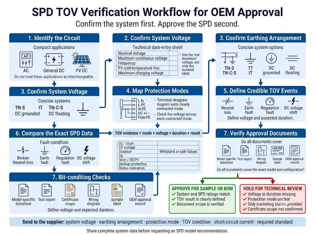
- Identifique o circuito. Separe as aplicações de rede CA, CC geral e PV solar. As caixas semelhantes não tornam os produtos intercambiáveis.
- Confirme a tensão máxima de funcionamento real. Inclua a tolerância de alimentação, comportamento do gerador ou transformador, tensão de carregamento ou tensão de baixa temperatura PV.
- Confirme o esquema de ligação à terra. Registe TN-S, TN-C-S, TT, IT ou o método de ligação à terra CC relevante.
- Mapeie todos os modos de proteção. Verifique os caminhos L-N, L-PE, N-PE, polo-a-polo e polo-a-terra conforme aplicável.
- Defina eventos de TOV credíveis. Analise a perda de neutro, falhas à terra, falhas de regulação e condições anómalas específicas da fonte.
- Compare os dados completos do SPD. Analise Uc ou Ucpv, UT, duração, resultado, Up, classificação de curto-circuito e disposição de desligamento.
- Verifique o âmbito do documento de aprovação. Confirme que a ficha técnica, o relatório e o certificado se aplicam à versão de tensão, configuração de polos e modelo exatos encomendados.
Informação a enviar antes de solicitar uma recomendação de modelo
- Tensão nominal do sistema
- Tensão contínua máxima
- Aplicação de CA, CC geral ou PV
- Frequência do sistema quando aplicável
- Esquema de ligação à terra
- Modos de proteção necessários
- Cenário de perda de neutro ou falha à terra
- Uc ou Ucpv em consideração
- Tensão e duração TOV exigidas
- Resultado de suportabilidade ou falha segura exigido
- Corrente de curto-circuito prospectiva
- Informações sobre fusível de reserva ou MCB
- Padrão ou certificado requerido
- Requisito de sinalização remota
- Quantidade e posição de instalação
- Requisito de rotulagem ou embalagem OEM
Confirme os dados do TOV antes de aprovar o modelo de SPD
Envie a tensão do sistema, o esquema de ligação à terra, os modos de proteção e as condições credíveis de tensão anormal. A LEEYEE pode ajudar a identificar quais os dados de Uc, Ucpv e TOV que devem ser verificados antes da aprovação da amostra ou da BOM.
CNSPD é a plataforma da LEEYEE focada em proteção contra sobretensões para compradores técnicos globais. Construído para Proteger. Confiável para Durar.
Compartilhe os detalhes do seu sistema para análiseO que deve ser verificado após um evento TOV suspeito?
Não instale um cartucho de substituição antes de identificar a tensão anormal original. Um novo SPD pode voltar a falhar se a falha no sistema persistir.
- Isole o circuito de acordo com o procedimento de segurança elétrica do local.
- Registe o indicador do SPD, o alarme remoto e a etiqueta completa do produto.
- Meça as tensões L-N, L-L, L-PE, N-PE ou de polo CC, conforme aplicável.
- Verifique a continuidade do neutro, a ligação à terra e o diagrama unifilar atual.
- Inspecione o cartucho, a base, os condutores, os terminais e a proteção de reserva.
- Reveja os registos do gerador, transformador, inversor, relé e eventos da rede elétrica.
- Confirme os dados de Uc, Ucpv, TOV de substituição e a configuração da proteção.
Para um processo de diagnóstico mais abrangente, utilize o relacionado Guia de causas de falha de SPD.
Perguntas frequentes sobre a resistência de TOV de SPD
Pode um SPD proteger equipamento contra uma sobretensão temporária?
Um SPD destina-se principalmente a limitar sobretensões transitórias. Normalmente, não regula nem elimina uma tensão de sistema anormal sustentada. Durante uma TOV, pode permanecer estável ou entrar na sua condição declarada de fim de vida controlado.
Pode uma TOV fazer um SPD arder?
Sim. A condução sustentada pode causar aquecimento, fuga térmica, desligamento ou danos graves. O resultado depende da tensão, duração, conceção do SPD, corrente de falha disponível e coordenação do dispositivo de proteção.
Um Imax maior melhora a suportabilidade à TOV?
Não necessariamente. Imax é um parâmetro de corrente de impulso. A adequação à TOV depende da tensão de funcionamento contínuo, modo de proteção, comportamento de TOV definido e conceção de desligamento.
Um Uc mais elevado evita todas as falhas por TOV?
Não. Um Uc mais elevado pode aumentar a margem de tensão contínua, mas a duração, o modo de proteção, a tecnologia do SPD e o comportamento de desligamento continuam a afetar o resultado.
A perda de neutro pode danificar um SPD de 275 V ou 320 V?
Pode. O deslocamento do neutro num sistema trifásico a quatro fios pode elevar a tensão num caminho de proteção L-N para muito acima do normal. O resultado depende da tensão real, da duração e do comportamento de TOV específico do modelo.
O que significa falha segura?
Significa que o desligamento controlado ou o fim de vida podem ser permitidos sob a condição de teste declarada. Não significa que o módulo continue a fornecer proteção contra sobretensões.
Ucpv é o mesmo que a tensão nominal de um sistema FV?
Não. Ucpv é a tensão máxima de funcionamento contínuo declarada para o SPD FV. Deve ser verificada em relação à tensão máxima calculada para o conjunto FV real e a configuração de proteção.
Que documentos sobre TOV deve um comprador OEM solicitar?
Solicite a ficha técnica do modelo exato, o diagrama do modo de proteção, Uc ou Ucpv, tensão UT, duração, definição de resultado, capacidade de curto-circuito, requisitos de proteção de reserva, instruções de instalação e âmbito do certificado.
Referências
- Comissão Eletrotécnica Internacional, IEC 61643-01:2024 — Dispositivos de proteção contra sobretensões de baixa tensão — Parte 01: Requisitos gerais e métodos de ensaio. Página de publicação oficial da IEC.
- Comissão Eletrotécnica Internacional, IEC 61643-11:2025 — Dispositivos de proteção contra surtos de baixa tensão — Parte 11: Dispositivos de proteção contra surtos conectados a sistemas de energia de baixa tensão em CA — Requisitos e métodos de ensaio. Página de publicação oficial da IEC.
- Comissão Eletrotécnica Internacional, IEC 61643-12:2020 — Dispositivos de proteção contra sobretensões de baixa tensão — Parte 12: Dispositivos de proteção contra sobretensões ligados a sistemas de potência de baixa tensão — Princípios de seleção e aplicação. Página de publicação oficial da IEC.
- Comissão Eletrotécnica Internacional, IEC 60364-4-44:2024 — Instalações elétricas de baixa tensão — Parte 4-44: Proteção para a segurança — Proteção contra perturbações de tensão e perturbações eletromagnéticas. Página de publicação oficial da IEC.
- Comissão Eletrotécnica Internacional, IEC 61643-41:2025 — Dispositivos de proteção contra sobretensões de baixa tensão — Parte 41: Dispositivos de proteção contra sobretensões ligados a sistemas de potência de baixa tensão em corrente contínua — Requisitos e métodos de ensaio. Página de publicação oficial da IEC.
- Comissão Eletrotécnica Internacional, IEC 61643-31:2018 e Errata 1:2022 — Requisitos e métodos de ensaio para SPDs para instalações fotovoltaicas. Página de publicação oficial da IEC.
- Comissão Eletrotécnica Internacional, IEC 61643-32:2017 e Errata 1:2019 — Dispositivos de proteção contra sobretensões ligados ao lado de corrente contínua de instalações fotovoltaicas — Princípios de seleção e aplicação. Página de publicação oficial da IEC.
- Comissão Eletrotécnica Internacional, IEC 60364-7-712:2025 — Instalações elétricas de baixa tensão — Instalações de fornecimento de energia solar fotovoltaica. Página de publicação oficial da IEC.
- D. Kladar, F. Martzloff e D. Nastasi, Efeitos de TOV em Dispositivos de Proteção contra Sobretensões, Eaton Electrical e EPRI Solutions, organizado pelo Instituto Nacional de Padrões e Tecnologia (NIST) dos EUA. Documento técnico organizado pelo NIST.
- ABB Furse, Guia de Produtos da Série de Proteção contra Surtos ESP Tipo 1 e Tipo 2, incluindo dados de Uc, UT, suportabilidade e falha segura específicos do modelo. Guia técnico oficial da ABB.
